Every clinician who has performed endodontics has experienced a variety of emotions ranging from the thrill-of-the-fill, to an upset such as the procedural accident of breaking an instrument. During root canal preparation procedures, the potential for instrument breakage is always present. When instrument breakage occurs, it immediately provokes despair, anxiety, and then the hope that nonsurgical re-treatment techniques exist to liberate the instrument from the canal.
Many clinicians associate “broken instruments” with separated files, but the term could also apply to a sectioned silver point, a segment of a lentulo, a Gates Glidden drill, a portion of a carrier-based obturator, or any other dental material left inside a canal.1,2 With the advent of rotary nickel-titanium (NiTi) files, there has been an unfortunate increase in the occurrence of broken instruments, and the factors contributing to breakage have been identified.3 The consequences of leaving versus removing broken instruments from a canal have been discussed in the literature, and a variety of approaches for managing these obstructions have been presented.4-6
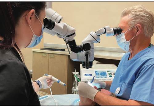
Today, separated instruments can usually be removed due to technological advancements in vision, ultrasonic instrumentation, and microtube delivery methods. Specifically, the dental operating microscope allows clinicians to visualize most broken instruments, and fulfills the age-old adage, “If you can see it, you can probably do it.” In combination, the microscope and ultrasonic instrumentation have driven “microsonic” techniques, which have dramatically improved the potential and safety of removing broken instruments.7-9
FACTORS INFLUENCING BROKEN INSTRUMENT REMOVAL
The factors influencing broken instrument removal should be identified and fully appreciated. The ability to nonsurgically access and remove a broken instrument will be influenced by the diameter, length, and position of the obstruction within a canal. The potential to safely remove a broken instrument is further guided by anatomy, including the diameter, length, and curvature of the canal, and additionally limited by root morphology, including the thickness of dentin and the depth of external concavities. In general, if one third of the overall length of an obstruction can be exposed, it can usually be removed. Instruments that lie in the straightaway portions of a canal can typically be removed. More challenging are separated instruments that lie partially around canal curvatures, but these can often be removed if straight-line access can be established to their most coronal extents. If the broken instrument segment is apical to the curvature of the canal and safe access cannot be accomplished, then removal is usually not possible and, in the presence of signs or symptoms, surgery or an extraction will at times be required.
The type of material comprising an obstruction is another important factor to be considered. For example, stainless steel files tend to be easier to remove, as they do not further fracture during the removal process. Nickel-titanium broken instruments may break again, albeit deeper within the canal, due to heat buildup during ultrasonic efforts. Whether a separated file’s cutting action was clockwise versus counterclockwise is important to visualize and know, as this factor will influence the correct ultrasonic removal technique.
Another factor that is central to successful instrument removal is integrating the best presently developed and proven technologies. Traditionally, retrieving broken instruments posed formidable challenges. One time-honored technique has been the use of small files to either remove, or at least bypass, the broken instrument. Over time retrieval techniques evolved, but were often ineffective because of limited vision and/or restricted space. Frequently, efforts directed toward instrument retrieval, even when successful, weakened a root with overzealous canal enlargement, which in turn predisposed to a hopeless fracture and the loss of a tooth. Indeed, the prognosis of a tooth can be seriously compromised if the efforts to remove a broken instrument lead to iatrogenic events, such as a ledged canal or root perforation. When retrieval efforts are unsuccessful, cleaning, shaping, and obturation procedures are compromised, and the ultimate prognosis is in doubt. Today, most broken instruments can be safely and efficiently removed with the use of advanced technologies and proper training.
ARMAMENTARIUM FOR BROKEN INSTRUMENT REMOVAL
High-speed rotary cutting tools are selected to create and refine straight-line coronal access into the pulp chamber. Cost-effective and highly efficient, surgical-length tapered diamonds can be used, with or without water, to flare the axial walls and finish all aspects of the access preparation. Diamond-coated burs are available in different lengths, diameters, tapers, and abrasive grits. Access refinements can be made safely and with precision when a surgical-length tapered diamond is rotated at a slow rpm. Precision and safety are further improved when the distal end of the diamond is used with a light brushing motion to carefully sand away material. As such, based on the specific procedural task, a tapered diamond can be chosen whose distal end has a thin and pointed, rounded, or ball-type configuration. Common sense should prevail when choosing rotary cutting burs versus ultrasonic instruments for finishing the access cavity. In my opinion, ultrasonic access refinement tips are needless, inefficient, and approximately six times more costly compared to rotary cutting instruments that accomplish the same task.
My preferred armamentarium for broken instrument removal is:
•Gates Glidden Drills. Gates Glidden (GG) drills (DENTSPLY Maillefer) sizes 1 to 6 have maximum diameters of 0.5, 0.7, 0.9, 1.1, 1.3, and 1.5 mm, respectively, and are used to create radicular access and a uniform tapering funnel to the obstruction.
 |
| Figure 1. The Satelec P5 piezoelectric ultrasonic unit has a wide incremental power range and provides controlled linear tip movement to enhance clinical performance. |
•Piezoelectric Ultrasonics. The Satelec P5 (DENTSPLY Tulsa Dental) is the piezoelectric ultrasonic unit of choice for performing endodontic treatment and re-treatment procedures (Figure 1). This unit affords precise working accuracy and has a broad power range, and its unique “feedback” system measures tip resistance, regulates tip movement, and reduces the potential for tip breakage.
•ProUltra ENDO-3, 4, 5 Tips. The ProUltra ENDO tips (DENTSPLY Tulsa Dental) afford a clinical breakthrough in nonsurgical ultrasonic instrumentation, as their contra-angled and parallel walls improve vision when working below the orifice. Additionally, the ENDO-3, 4, and 5 are stainless steel instruments coated with zirconium nitride to improve durability and cutting efficiency (Figure 2a). Importantly, zirconium nitride resists corrosion regardless of the irrigant employed, does not flake off during use, and provides safe efficiency when performing delicate and precise intracanal procedures, as compared with more aggressive diamond coatings. The ProUltra instruments are used on the lower power settings, and have been designed to intentionally work dry.
 |
 |
| Figure 2a. The ProUltra ENDO-3, 4, and 5 ultrasonic instruments’ parallel walls and zirconium nitride coatings improve access, vision, and clinical efficiency. | Figure 2b. The ProUltra ENDO-6, 7, and 8 are titanium ultrasonic instruments that have longer lengths and smaller diameters to facilitate deeper “microsonic” techniques. |
•ProUltra ENDO-6, 7, 8 Tips. The ENDO-6, 7, and 8 ultrasonic instruments are made of titanium to provide clinicians with thinner diameters and longer lengths than the ENDO-3, 4, and 5 (Figure 2b). These instruments are utilized on the lower power settings, work dry, and are employed to perform procedures in deeper spaces where access is more restrictive.
•Stropko. The Stropko three-way adapter (Vista Dental) is used for collimating and directing air into the operating field. The Stropko blows out dentinal dust during ultrasonic use and provides constant vision. This adapter’s proximal end is placed into the three-way syringe, and its distal end has luer-lock threads for securely attaching different length and gauged canuli.
 |
| Figure 3. The iRS is a device for engaging and removing broken instruments. Each iRS is composed of a different gauge microtube and screw wedge. |
•Instrument Removal System (iRS). The iRS (DENTSPLY Tulsa Dental) is a new two-component system designed to mechanically engage broken instruments (Figure 3). Each microtube has a small plastic handle to enhance vision during placement, a side window to improve mechanics, and a 45° beveled end to “scoop up” the coronal end of a broken instrument. Each screw wedge has a knurled metal handle, a left-handed screw mechanism, and a solid cylinder that becomes tapered toward its distal end to facilitate engaging an obstruction.
 |
| Figure 4. The PRS kit is composed of five variously sized trephines and corresponding taps, a transmetal bur, rubber stamps, a torque bar, and the extracting pliers. |
•Post Removal System (PRS). The PRS kit (SybronEndo) contains several component parts that may be utilized to mechanically form threads and engage any obstruction whose diameter is 0.6 mm or greater (Figure 4). Specifically, the No. 1 and No. 2 taps will often grasp intracanal obstructions that extend into the pulp chamber, such as a silver point or carrier-based obturator.
•Magnification and Lighting. Magnification glasses, headlamps, fiber-optic transilluminating devices, and dental operating microscopes contribute to better vision. Specifically, the microscope provides options in magnification and coaxial light to promote superior vision. The microscope is a practice-building instrument that promotes professional growth, improves technical results, and distinguishes a practice in its community.
TECHNIQUES FOR BROKEN INSTRUMENT REMOVAL
Prior to commencing retrieval efforts, special attention is directed toward preoperative radiographs and working films to better appreciate the thickness of the dentinal walls and, if present, the depth of an external concavity. Coronal access is the first step in the removal of broken instruments. High-speed, friction-grip, surgical-length burs are selected to create straight-line access to all canal orifices. Special attention should be directed toward flaring the axial wall that approximates the canal holding the broken instrument in efforts to subsequently improve microsonic techniques below the orifice. (Note: The most important techniques for broken instrument removal have been clearly illustrated and clinically shown in the “Ruddle on Retreatment” video series.10)
With safety in mind, radicular access is the second step required in the successful removal of a broken instrument. If radicular access is limited, hand files are used serially small to large, coronal to the obstruction, to create sufficient space to safely introduce GG drills. GGs are rotated at speeds ranging between 800 to 900 rpm and, importantly, are used like “brushes” to create additional space and maximize visibility coronal to the obstruction. Increasingly larger GGs are uniformly stepped out of the canal to create a smooth-flowing funnel that is largest at the orifice and narrowest at the obstruction. GG drills should be limited to the straightaway portions of the canal, with no effort made to carry them around the curve in the event the instrument lies apical to the curvature. A GG-1 (0.50 mm) or GG-2 (0.70 mm) can usually be carried to the depth of the separated instrument. The GGs are used cautiously in approximation to the obstruction with attention to brush-cutting out of the canal and away from furcal danger. Relocating the coronal one third of a canal away from the furcation reduces the potential for root thinning or a strip perforation, and improves straight-line radicular access. The GG-3 (0.90 mm) is carried short of the level where the GG-2 was used and, in furcated teeth, the GG-4 (1.10 mm) is confined to a depth of no more than one bud length below the orifice. Importantly, radicular access should be performed so that the canal is pre-enlarged and ideally shaped no bigger than it would otherwise be prepared if there was no broken instrument obstructing the canal.
 |
| Figure 5. A photograph shows selected GG drills and their subsequent modification. |
When the canal has been optimally shaped, then microsonic techniques may be employed to remove a broken file segment. At times, when an ultrasonic instrument is introduced into a pre-enlarged canal, its activated tip does not have enough space lateral to the broken file segment to initiate trephining procedures. As such, if greater access is required lateral to the most coronal aspect of the obstruction, the bud of a GG can be “modified” and then used to create a circumferential “staging platform.”8,9 The staging platform is made by selecting a GG drill whose maximum cross-sectional diameter is slightly larger than the visualized instrument. The bud of the GG drill is altered by cutting it perpendicular to its long axis at its maximum cross-sectional diameter (Figure 5). The modified GG drill is gently carried into the pre-enlarged canal, rotated at a reduced speed of 300 rpm, and directed apically until it lightly contacts the most coronal aspect of the obstruction. This clinical step creates a small staging platform that facilitates the introduction of an ultrasonic instrument. When properly performed, straight-line coronal and radicular access, in conjunction with magnification and lighting, should enable the clinician to fully visualize the coronal-most aspect of a broken instrument. To facilitate excellent vision to the intra-radicular obstruction, the canal should be vigorously flushed and thoroughly dried prior to beginning ultrasonic procedures.
ULTRASONIC TECHNIQUES
 |
| Figure 6a. A graphic shows how a staging platform can facilitate the strategic placement of an ultrasonic instrument lateral and against the separated file. |
Prior to performing any radicular removal techniques, it is wise to place cotton pellets over other exposed orifices, if present, to prevent the nuisance re-entry of the fragment into another canal system. An appropriately sized ProUltra ENDO instrument is then selected, such that its length will reach the broken obstruction and its diameter will passively fit into the previously shaped canal. The tip of this ultrasonically selected instrument is placed in intimate contact against the obstruction and typically activated within the lower power settings (Figure 6a). The clinician should always work at the lowest power setting that will efficiently and safely accomplish the clinical task. All ultrasonic work below the orifice is conducted dry so the clinician has constant visualization of the energized tip and the broken instrument. To maintain vision, the dental assistant utilizes the Stropko three-way adapter with the appropriate luer-lock tip to collimate and direct a continuous stream of air, and blow out dentinal dust.
Recently, certain nonsurgical ultrasonic instruments have become available with water port technology. Although claims have been made that water port technology increases the life of these tips, there have never been any scientific or clinical studies to support these assertions. In my opinion, water port technology in nonsurgical ultrasonic instruments is contraindicated for four important reasons: (1) water flowing through an ultrasonic instrument dampens movement and decreases tip performance; (2) small diameter ultrasonic instruments are weakened and more predisposed to expensive breakage when they are machined for internal water flow; (3) there is an undesirable aerosol effect regardless of where the water port is positioned on an ultrasonic instrument; and (4) most importantly, no water should be used during nonsurgical ultrasonic procedures because moisture, in combination with dentinal dust, creates mud, lost vision, and the potential for iatrogenic outcomes.
In summary, clinical experience supports the vast majority of all nonsurgical ultrasonic procedures being performed dry, at the lowest power setting that will safely accomplish the clinical task, and utilizing a light brush-cutting action. Microsonic techniques, as advocated for removing broken instruments, do not generate sufficient heat to become harmful to the attachment apparatus. However, if ultrasonic procedures are performed at higher energy levels, for longer periods of time, and against larger, conductive objects such as a metal post, then the dental assistant should simply use a triplex syringe with an intermittent water spray to reduce heat buildup and transfer. Fortunately, heat does not conduct well through dentin, and is further rapidly dissipated due to the moisture content in the attachment apparatus.
 |
 |
| Figure 6b. A graphic shows an abrasively coated ultrasonic instrument trephining and progressively sanding away dentin to expose the head of a broken file. | Figure 6c. A graphic demonstrates using a longer length and smaller diameter titanium ENDO-6 ultrasonic instrument when space is more restrictive. |
 |
 |
| Figure 7a. An endodontically failing mandibular first molar. Note a short screw post, a separated instrument, and amalgam debris from the hemisection procedures. | Figure 7b. A photograph shows the splint removed, the post out, and an ultrasonic instrument trephining around the broken file. |
 |
 |
| Figure 7c. A post-treatment radiograph reveals three-dimensional re-treatment. Note the third mesial system between the MB and ML canals. | Figure 7d. An 8-year recall film demonstrates a new bridge and excellent periradicular healing. |
The selected ProUltra ENDO instrument is moved lightly in a counterclockwise direction around the obstruction, except when removing a file that has a left-handed thread, in which case the direction would be clockwise. This ultrasonic action trephines, sands away dentin, and exposes the coronal few millimeters of the obstruction (Figure 6b). Typically, during ultrasonic use the obstruction begins to loosen, unwind, and then spin. Gently wedging the energized tip between the tapered file and the canal wall often causes the broken instrument to abruptly “jump out” of the canal. In the instance where a broken file lies deep and ultrasonic procedures are restricted by root bulk and form, select an abrasively coated ultrasonic instrument with a longer length and smaller diameter to promote safe retrieval efforts. In longer roots, or when space is even more restrictive, an appropriately sized ProUltra titanium instrument may be chosen. The ProUltra titanium instruments have longer lengths and smaller diameters compared to the abrasively coated instruments, and their smooth cutting action promotes safety when trephining deeper within a canal (Figure 6c). Exposing 2 to 3 mm of the coronal-most aspect of an obstruction, or about one third of its overall length, will generally produce the desired result. The clinical steps for broken instrument removal utilizing microsonics are shown in Figures 7a through 7d.
On occasion, the clinician may create excellent coronal and radicular access, identify and expose the separated instrument, perform ultrasonic trephining procedures, and still be unable to loosen and “jettison” the instrument out of the canal. Further, it may be unsafe to continue trephining around a broken instrument because of lack of vision or anatomical restrictions. In these instances, and as a last ultrasonic resort, the handle from a stainless steel hand file can be intentionally removed and the shaft of the instrument inserted into a device called the File Adapter (SybronEndo). The File Adapter threads onto the ultrasonic handpiece, and its chuck will retain a 0.02 tapered hand file. Although tedious, small stainless steel hand files can be precurved as indicated, inserted into available space, and used at low power in an ultrasonic effort to remove a broken instrument. This technique is at times useful when the root is thin and/or the canal is curved. When 2 to 3 mm of a broken instrument have been exposed and if ultrasonic procedures prove unsuccessful, then an alternative removal method is to utilize a microtube device to mechanically engage and potentially remove the obstruction. For a variety of reasons, I prefer a mechanical microtube device over the more traditional “tube and glue” approaches.
MECHANICAL MICROTUBE OPTIONS
Microtube Tap and Thread
The PRS contains certain microtubular taps that allow the clinician to form threads and mechanically engage the most coronal aspect of any obstruction whose diameter is 0.6 mm or greater. These microtubular taps contain a reverse thread, and engage an obstruction by turning in a counterclockwise motion. The outside diameter of the smallest microtubular tap generally limits its use to the coronal one third of larger canals; however, these microtubes can tap, form threads, and engage a variety of radicular obstructions that extend coronally into the pulp chamber. Caution should be used to not over-thread an obstruction, such as a silver point, so it does not bottom-out and shear off inside the lumen of the tap. Once the obstruction is securely engaged by the microtubular tap, the extracting plier is utilized with a protective bumper to cushion the removal force.
Tube Mechanics
Another technique that has been advocated to remove broken instruments utilized a microtube and a hedstroem file. With limitations, this method of removal involved sizing and gauging the correct microtube so it could reach, and be placed over, the ultrasonically exposed obstruction. Microtube sizes that were clinically relevant were 18, 20, and 22 gauge (Spinal Tap Needle, Ranfac). Because of their unique ability to engage, a 35, 40, or 45 hedstroem was selected and, when possible, inserted into the coronal-most aspect of the microtube. The hedstroem was then passed down the length of the tube until it was engaged tightly between the obstruction and the internal lumen of the microtube. Although limited by space, this removal method could, at times, successfully retrieve obstructions from larger canals. Presently, an innovative mechanical device known as the Instrument Removal System (iRS) has been developed for the retrieval of broken instruments in more restrictive spaces.
The Instrument Removal System
The iRS provides a procedural breakthrough for the removal of intracanal obstructions such as silver points, carrier-based obturators, or broken file segments. The iRS is indicated when ultrasonic efforts prove to be unsuccessful, and may be used to remove broken instruments that are lodged in the straightaway portions of the root or partially around the canal curvature.9,10 The instrument with the black handle is 19 gauge (1 mm), and is designed to work in the coronal one third of larger canals, whereas the instrument with the red handle is 21 gauge (0.80 mm), allowing it to be placed deeper into more narrow canals. Each complete instrument is composed of a color-coordinated microtube and screw wedge.
As has been emphasized for any removal technique, and is essential for the success of the iRS, straight-line coronal and radicular access is required to expose and subsequently visualize the coronal-most end of the broken instrument. As previously described, the clinician utilizes ultrasonic instrumentation to circumferentially expose 2 to 3 mm of the separated file. However, ultrasonic instruments can only circumferentially trephine, sand away dentin, and expose the portion of the obstruction that lies in the straightaway portion of the canal. Therefore, the goal is to expose 2 to 3 mm, or about one third of the total length, of a separated instrument.
 |
 |
| Figure 8a. This 21-guage iRS is a two-component device composed of a microtube and screw wedge for mechanically removing broken instruments. | Figure 8b. This graphic illustrates the beveled end of the microtube oriented toward the outer wall of the canal to “scoop up” the head of the broken file. |
 |
 |
| Figure 8c. This graphic shows the introduction of the screw wedge which is rotated counterclockwise to engage and displace the head of the file out the side window. | Figure 8d. This graphic demonstrates the mechanical advantage of utilizing the iRS to liberate the broken instrument from the canal. |
 |
 |
| Figure 9a. A preoperative radiograph of a maxillary canine demonstrates a temporized canal with an instrument broken deep in the apical one third. | Figure 9b. A working film shows that the 21-guage iRS has successfully engaged and partially elevated the deeply positioned file segment. |
 |
| Figure 9c. A postoperative film demonstrates the re-treatment steps and a densely packed system that exhibits three apical portals of exit. |
A black- or red-handled microtube is then selected that can passively slide through the pre-enlarged canal and drop over the exposed broken instrument (Figure 8a). In a curved canal, it is axiomatic that the head of a broken NiTi file will always lie against the outer wall. In these instances, the microtube is inserted into the canal with the long part of its beveled end oriented to the outer wall of the canal to “scoop up” the head of the broken instrument and guide it into the microtube (Figure 8b). Once the microtube has been positioned, the same color-coded screw wedge is inserted and slid internally through the microtube’s length until it contacts the obstruction. The obstruction is engaged by gently turning the screw wedge handle counterclockwise. A few degrees of rotation will serve to tighten, wedge, and often displace the head of the obstruction through the microtube window (Figure 8c). If a screw wedge with a specifically marked color is unable to achieve a strong hold on the obstruction, then the other gauge and color-coded screw wedge should be selected to encourage engagement and removal. When engaged, the obstruction is removed by rotating the microtube and screw wedge assembly out of the canal. In the instance of a broken file, the direction of rotation is generally counterclockwise, but ultimately should be appropriate to the thread design of the obstruction (Figure 8d). If difficulty is encountered when rotating the microtube and screw-wedge assembly counterclockwise, then proceed with a limited clockwise rotation of 3° to 5°, which will promote staying engaged, followed by turning the assembly counterclockwise until snug. This repeated reciprocating handle motion will serve to loosen the obstruction and facilitate the removal process.
Placing an activated ProUltra ENDO-1 tip on the engaged assembly is another potent adjunct that will promote removal success. If a microtube cannot be placed over a broken instrument such that the head of the obstruction lies within the side window, the microtube’s beveled end can be easily reduced or eliminated to achieve better mechanics. A clinical case utilizing the iRS option is shown in Figures 9a through 9c.
CONCLUSION
The best antidote for a broken file is prevention. Adhering to proven concepts, integrating best strategies, and utilizing safe techniques during root canal preparation procedures will virtually eliminate the broken instrument procedural accident.11,12