


INTRODUCTION
Partially edentulous arches are the cases that are most frequently treated with implants in the average dental practice. Patients lose teeth for a variety of reasons, including periodontal bone loss, endodontic failures, and non-restorability of a tooth that may be related to caries or trauma.
Implants can be placed free-hand or guided. Free-hand placement has the potential for a number of errors that can make restoration challenging, damage the adjacent teeth, or create spacing issues that may lead to periodontal problems over time. Typically, the alternative has been guided placement with a lab-fabricated guide. One version of lab-fabricated guides is done by the laboratory technician, who sets denture teeth in the space and constructs an acrylic guide with a hole in the center of the tooth to guide the pilot drill, thus helping to ensure proper spacing and orientation. Other alternatives involve drilling a pilot hole in the study model, inserting a pin and a guide sleeve over it, and fabricating an acrylic surgical stent. This type of stent can be used to guide only the pilot drill or all of the drills to be used to create the osteotomy. More complex guides are possible that utilize CBCT scans, virtual implant placement in software (either performed by the practitioner or lab during planning), and CAD/CAM milled guides based on virtual placement. These CAD/CAM guides have switchable metal sleeves that allow guidance of all osteotomy drills that will be used during the surgery.
A negative issue with guides made in the dental laboratory is the fabrication time needed to design and construct the guide. Even in simple cases, there can be a delay of up to 2 weeks before implant surgery can be performed to place implants into a partially edentulous space. And, in thinking about this further, are these lab-fabricated guides even necessary when only placing a single implant bounded by natural teeth (or restored implants) or for a space that will accommodate 2 adjacent implants that have teeth mesial and distal to the edentulous space? If we understand what may go wrong in placing implants in these 2 situations, we can simplify the process of surgical placement.
 |
 |
| Figure 1. The IVIS (Implant Vision Implant System) Implant Guidance System (Mediquip Implant Supplies) kit for implant guidance in partially edentulous sites that will have one or 2 (adjacent) implants placed. | Figure 2. The IVIS Implant Guidance System guide tabs to accommodate different widths of single or double sites, based on the planned implant diameter, and a guide tab for narrow sites or single mini implants. |
 |
 |
| Figure 3. The IVIS Implant Guidance System handle (top) and with the guide tab inserted into the handle (bottom). | Figure 4. IVIS Implant Guidance System guide pins, shown wingless (top), with horizontal wings (middle) for spacing of implants planned for different diameters, and with a visualization of the wings on each size pin (bottom). |
Potential problems when placing an implant into a single or double site include placement that can be too far buccal or lingual, leaving insufficient space between the implant and adjacent tooth or between implants being placed next to each other. Free-hand placement may lead to these complications, which can make the restoration phase of treatment challenging, especially in the aesthetic zone. An implant placed too buccal or facial will likely not blend well with the adjacent teeth, and this also complicates the work for the lab technician, who must create an abutment and crown to restore that implant. Of course, placement too far lingually is usually less of a complication to the desired aesthetic outcome. Orientation in the mesial-distal dimension may yield complications more closely related to periodontal concerns than aesthetics. When insufficient space is provided between the implant and adjacent tooth, the papilla is often lost either initially or over time, leading to bone loss. This may be challenging to some patients to keep clean and can also complicate lab fabrication due to insufficient space to accommodate the minimal thickness of the abutment and overlaying crown. A screw-retained crown may solve this dilemma but may not always be applicable clinically for a particular site and patient situation. Additionally, when the implant is not centered in the space and placed too close to the adjacent tooth on one side, a wider space is left on the other proximal surface, leading to emergence profile issues and the consequential food trap under the proximal contact. So, free-hand placement should be avoided in most cases to obviate those potential complications.
Is there a simplified approach that could be considered?
Guided Implant Surgery for Partially Edentulous Spaces
A kit has been developed that eliminates the problems that occur when placing single or 2 adjacent implants when the space is bounded by teeth. The IVIS (Implant Vision Implant System) Implant Guidance System (MedEquip Implant Supplies) provides guidance tabs and pins to allow proper orientation in the buccal-lingual and mesial-distal directions when creating an osteotomy (Figure 1). The guide tabs can accommodate the placement of 3.0-mm, standard diameter (SD, 3.3 to 3.6 mm), regular diameter (RD, 3.75 to 4.3 mm), and wide diameter (WD, 5.0 to 5.5 mm) implants (Figure 2). Each guidance tab is designed for either the placement of a single implant (front of tab) or 2 adjacent implants (back of tab), and they have lateral wings to orient the implant osteotomy based on the cervical of the adjacent teeth. Additionally, a guidance tab is provided for narrow sites that may present at a maxillary lateral or mandibular incisor placement, requiring either a narrow diameter implant or mini implant due to the available mesial-distal space present (Figure 2). The kit contains a handle to hold the guidance tab during surgery, permitting use in all areas of the arch (Figure 3). When utilizing the tab for single implant placement, spacing of 2.0 mm from each adjacent tooth is designed for ideal placement from the adjacent teeth. The double-implant portion of the guidance tab also sets spacing of 2.0 mm from the adjacent tooth and an ideal 3.0 mm between implants.
 |
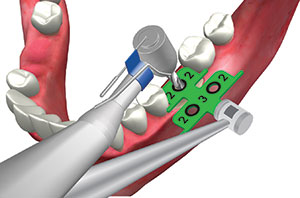 |
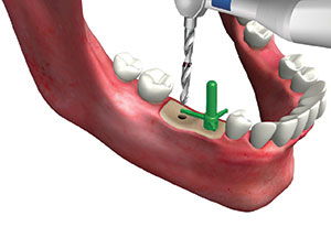
| Figure 5. IVIS Implant Guidance System guide tab placed into a single site that fits the mesial-distal dimension, with the wings contacting the adjacent teeth to position the initial osteotomy equidistant between the teeth and at the midcrest based on the buccal of those teeth. | Figure 6. A pilot drill, introduced through the IVIS Implant Guidance System guide tab to initiate osteotomy site preparation in an ideal position based on the space width and adjacent teeth positions. |
 |
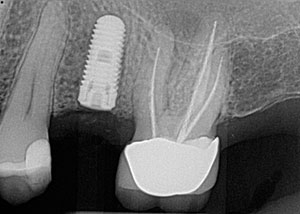 |
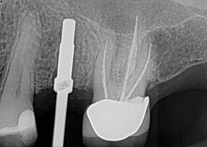
| Figure 7. A radiograph following the placement of a single implant into the maxillary left central incisor using the IVIS Implant Guidance System, demonstrating proper spacing between the adjacent teeth. | Figure 8. A radiograph following the placement of a single implant into the maxillary second premolar site using the IVIS Implant Guidance System, demonstrating proper spacing between the adjacent teeth. |
 |
 |
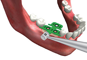
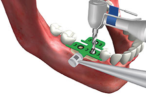
| Figure 9. When 2 implants are planned due to a larger mesial-distal dimension, the 2-implant portion of the IVIS Implant Guidance System guide tab is inserted that fits the width of the site. | Figure 10. A pilot drill is introduced into the distal guide hole on the positioned IVIS Implant Guidance System guide tab to place an initial osteotomy. |
Guidance pins in the kit come in 2 forms that allow one end to be used in the site following pilot hole creation and the other end to be used following the use of wider osteotomy drills. The pins are color coded similarly to the guidance tabs (Figure 4). One set of pins (Measuring Pin) has horizontal blades to verify spacing following pilot drill use with the guidance tab. The blades measure 2.0 mm (to verify space to the adjacent tooth) and 3.0 mm (to verify space between implants) with a longer notched tab to create a pilot hole when there is no distal tooth with which to use the guidance tab. The other set of pins (Parallel Pin) can be placed into the second pilot osteotomy to verify parallelism with the Measuring Pin. Following pilot hole creation, a radiograph can be taken with the guidance pins in place to verify spacing to adjacent teeth and anatomical structures and parallelism to adjacent teeth.
Single Implant Guided Placement
A guidance tab is tried into the edentulous space so that the front portion of the tab fits into the space with little mesial-distal sliding and the wings are contacting the cervical of the adjacent teeth (Figure 5). Should the tab be able to slide mesially and distally, the next size guidance tab is tried in to verify if it fits the edentulous space better (with less lateral movement possible). A pilot drill is introduced through the hole in the guidance tab, paralleling the drill with the long axis of the adjacent teeth (Figure 6). It is recommended that the pilot drill be taken to half the planned depth, a Parallel Pin placed, and then a radiograph taken to verify orientation to adjacent teeth and anatomical structures. Following confirmation, the guidance tab is reinserted, and the pilot drill is taken to the full planned depth. The osteotomy is completed with wider drills without the guidance tab intraorally. The system may be used in the anterior (Figure 7) or posterior (Figure 8) to guide implant placement.
Double Adjacent Implant Guided Placement
As with use of the guidance tabs for single implant placement, when using them for 2 adjacent implants, the starting process is similar. A guidance tab (bottom portion) is selected to fit into the edentulous space that has minimal mesial-distal movement when inserted (Figure 9). The guide tab is utilized to initiate the distal osteotomy with the pilot drill to half the planned depth (Figure 10), and then the mesial osteotomy is performed in an identical manner (Figure 11).
A winged Measuring Pin that matches the planned implant diameter is inserted into the mesial hole and rotated until the 2.0-mm wing contacts the middle of the proximal of the adjacent tooth (Figure 12). A radiograph may be taken at this point to verify orientation, if desired (Figure 13).
 |
 |
| Figure 11. The pilot drill is then introduced into the mesial hole on the Implant Vision guide tab to position the 2 initial osteotomies at a proper distance from the adjacent teeth and between the planned implants. | Figure 12. An IVIS Implant Guidance System guide pin reflecting the diameter of the planned implant is placed into the mesial osteotomy and rotated until the 2- or 3-mm horizontal tab (depending on desired distance) contacts the mid-proximal of the adjacent tooth, and a radiograph may be taken to verify distance and angulation as well as proximity to anatomy. |
 |
 |
| Figure 13. A radiograph of an IVIS Implant Guidance System guidance pin in an initial osteotomy to verify distance to the adjacent root and anatomical features. | Figure 14. The IVIS Implant Guidance System guidance pin is rotated so that the long tab is pointed at the distal initial osteotomy to confirm the distance between the 2 sites, and an osteotomy drill is introduced into the distal site parallel to the mesial pin. |
 |
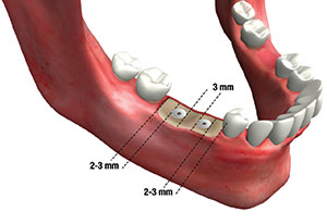 |
| Figure 15. A guide pin of the planned implant diameter is inserted into the distal site, and the 2.0- or 3.0-mm horizontal tab on the mesial pin is rotated to contact the distal guide pin to verify spacing of the parallel guide pins. | Figure 16. The IVIS Implant Guidance System allows ideal spacing of implants in a 2-implant space that positions the implants at a proper distance from adjacent teeth and between the implants. |
 |
| Figure 17. A radiograph of 2 adjacent implants placed in the posterior using the IVIS Implant Guidance System, demonstrating proper spacing of the implants from the natural teeth and between the implants, as well as demonstrating parallelism between the implants. |
The notched wing is rotated to the second site, and the pilot drill is paralleled to the pin to the full depth of the drill using the notch as orientation point (Figure 14). A guide pin for the planned implant diameter is inserted into the distal site, and then the 2.0- or 3.0-mm horizontal tab on the mesial pin is rotated to contact the distal guide pin to verify spacing of the parallel guide pins (Figure 15). Guide pins can be placed into the initial sites, and then a radiograph is taken to confirm orientation and parallelism of the implants before proceeding. The distal osteotomy can be completed utilizing the mesial pin for parallelism. The wider end of the pin is then placed into the distal osteotomy, and the mesial osteotomy is then completed using that pin for parallelism. The guidance system provides ideal spacing between the implants and adjacent teeth as well as between the implants (Figures 16 and 17). As with the single implant portion of the tab, the double implant portion of the guidance tab may be used in the anterior or posterior to guide implant placement.
IN SUMMARY
When indicated, using the IVIS Implant Guidance System, a simpler alternative to lab-fabricated guides, can be an easy and reliable option when a single implant or 2 adjacent implants are being placed. The guidance tabs use the adjacent teeth to orient the initial osteotomy in both the mesial-distal and buccal-lingual dimensions to create ideal spacing with the adjacent teeth or between implants. The same sequence for adjacent implant placement may be used when no distal tooth is present. The guide tab is utilized to create the mesial implant initial osteotomy, and then the pins are utilized as previously described to orient and create the distal osteotomy. One key benefit of the guidance system is treatment may be accomplished in a more efficient way for the patient and doctor since there is no delay while waiting on the laboratory fabrication of a custom surgical guide.
Dr. Garg is a nationally recognized dental educator and surgeon who, for more than 20 years, served as a full-time professor of surgery in the department of Oral and Maxillofacial Surgery and as director of residency training at the University of Miami Leonard M. Miller School of Medicine. Dr. Garg is considered the world’s preeminent authority on bone biology, bone harvesting, and bone grafting for dental implant surgery. He is a well-known lecturer and has authored 9 published text books and a dental implant marketing kit that have been translated into multiple languages and distributed worldwide. He can be reached at arun.implantseminars@gmail.com.
Dr. Kurtzman is in private general practice in Silver Spring, Md. A former assistant clinical professor at the University of Maryland, he has earned Fellowships in the AGD, the American Academy of Implant Prosthodontics, the American College of Dentists, the International Congress of Oral Implantologists (ICOI), the Pierre Fauchard Academy, and the Association of Dental Implantology; Masterships in the AGD and ICOI; and Diplomate status in the ICOI and the American Dental Implant Association. He has lectured internationally, and his articles have been published worldwide. He has been listed as one of Dentistry Today’s Leaders in Continuing Education since 2006. He can be reached via email at dr_kurtzman@maryland-implants.com.
Dr. Rezakhani received her DMD degree from Nova Southeastern University. She is an experienced general dentist with a demonstrated history of working in the hospital and healthcare industry. Dr. Rezakhani is a healthcare services professional who is skilled in endodontics, teeth whitening, veneers, cosmetic dentistry, crowns, implants, and full-mouth reconstruction. She can be reached via email at niloufar30@gmail.com.
Disclosure: The authors report no disclosures.
Related Articles
6-Part Series Explores the Evolution of Comprehensive Care
Laser Troughing to Improve Scanning and Impressions
Replacement of a Failing Composite Restoration: Pairing a Self-Etch Adhesive and Nanocomposite


