The first article of this series discussed the principles of Bioesthetic Dentistry and the preliminary diagnosis based on those principles. The preliminary occlusal diagnosis was made on models mounted in a centric related position of the condyles (not stabilized), evaluating the form and function in the patient’s gnathic system.
The second article discussed the importance of adhering to natural genetic form in restoring the chewing system, since Bioesthetic Dentistry accepts natural form as the basis for comprehensive diagnosis and rehabilitation. These first 2 articles may be read in the digital editions of Dentistry Today at dentistrytoday.com.
The case represented here and in part 4 of this series will discuss the Bioesthetic principles of restorative treatment, from preliminary diagnosis through case delivery. The case used involves an uncomfortable bite, maxillary anterior wear, and wear on the mandibular canines.
CASE REPORT
Diagnosis and Treatment Planning
A 32-year-old male patient presented with an uncomfortable bite, wear of the maxillary anterior dentition, and wear on the mandibular canines. The patient had 2 options for selection of the treatment:
First, he could have opted to restore the lengths of the maxillary anterior teeth and the mandibular canines with veneers. This selection would have solved the problem of anterior esthetics, but it would not have addressed the long-term health and welfare of the complete mastication/chewing system. Because of the avoidance patterns, set up by the centric occlusion (CO) and centrically-related occlusion (CO/CR) discrepancy, the veneers would have been at high risk of fracture or delimitation, and severe wear on the opposing incisors due to off-axis loading.
The second option was to treat the entire system by following 3 principles:
- Stabilize the joint in harmony with maximum intercuspal position (MIP) to eliminate the CO/CR discrepancy.
- Recreate the sharp, unworn form to the teeth with intraoral coronaplasty procedures (subtractive and additive) in order to guard the chewing system from overloads.
- Reinstate the form of the anterior teeth with veneers to re-establish the proprioceptive anterior guidance.
The patient selected the comprehensive approach for long-term health and appearance. The treatment plan in this case was to first stabilize the temporomandibular joint (TMJ) by the use of a maxillary anterior guided orthotic (MAGO). The confirmation of joint stability was to be determined by the use of periodic open bite centric records and adjustments to the MAGO until a stable joint position could be demonstrated on the axis position indicator (API) instrument (Panadent Corp).
After achieving a stable position of the joint, an axis recording would be taken to locate the hinge axis to determine the condylar angle and the extent of the Bennett movement. This information, along with new stone models, would be transferred to the articulator (Panadent Corp). These models, representing the patient in a stable condylar position (SCP), would then be used to perform an external coronaplasty and create a wax-up of the desired final results. The dental laboratory could also use the wax-up to fabricate a mold for the practitioner to construct temporary crowns, or use it as a guide in replacing tooth form with the composite materials. In turn, the provisional restorations would be evaluated and used to obtain approval from the patient for the appearance and function of the final restorations. The desired end result would be a stable, esthetic, comfortable, long lasting dentition.
Clinical and Laboratory Procedures
The patient was treated with splint therapy, using a MAGO appliance on the maxillary arch. The orthotic was placed and adjusted until the TMJs assumed their most superior/anterior medial stable position in the fossa. The appliance also allowed the joints and muscles to heal from any inflammation caused by neuromuscular disharmony, due to tooth interferences during movement and closure. The MAGO appliance also programs the central nervous system for verticalized closure and gives a stable healthy position from which to diagnose and treat the patient.
 |
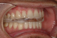 |
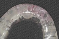
| Figure 1. Initial anterior contacts and incisive/surtrusive pathways. Anterior contacts only for first 24 to 72 hours. | Figure 2. Posterior contacts and canine guidance additions with acrylic resin. |
 |
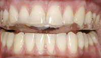 |
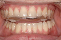
| Figure 3. Left canine guidance. Note the clearance of 2 to 3 mm between the appliance and the mandibular posterior teeth on the nonchewing side and 1 to 2 mm of clearance on the chewing side. | Figure 4. The incisive test position. There is clearance of 2 to 3 mm in the posterior region. |
After checking and adjusting the appliance to fit the teeth accurately, the next procedure was to create an even contact on the anterior acrylic area of the appliance between the 2 mandibular central incisors and the mesial aspect of the incisal edges of the 2 mandibular lateral incisors. No CR contact of the mandibular canines was permitted in order to avoid any tendency of the appliance to force either condyle out of the fossa. An 8-µm Mylar ribbon was used to ensure that the 4 contacts were equal in intensity (Figure 1). The posterior area of the appliance was left at least 2.0 mm out of contact.
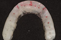
The patient wore the orthotic for 2 days (24 hours per day, except for brushing and flossing). On the third day (Figure 2), acrylic was added to the posterior area to create contacts between the mandibular posterior teeth (one mark per centric cusp) and the appliance. Canine guidance (Figure 2) was also added by processing acrylic to the MAGO to ensure that no posterior contacts were present on the appliance in excursive movements of the mandible (Figures 3 and 4). Again, the canine area of the appliance was left slightly out of contact with the opposing mandibular canine. Any interfering contacts in the incisive/surtrusion (upward) and right and left medial/surtrusion pathways were removed (Figure 5). Once a week, for 6 weeks, the appliance was “challenged” with the use of several 0.003 tin foil shims (Buffalo Dental) placed on the anterior area of the appliance (Figure 6). The anterior metal shims separated the mandibular posterior teeth from the appliance (Figure 6), recreating a Class III lever. The shims were removed, one at a time, marking the posterior area with 12-µm thick Mylar articulating paper (such as Accufilm II [Parkell]), until a contact point was observed. The initial premature occlusal contacts were adjusted, ie, removed, using fine carbide burs and Cratex wheels. The process of removing the shims—one at a time—was repeated until even contacts were developed on the posterior and anterior teeth. During the last 3 weeks, the condyles were determined to be stable in position, by utilizing the API (Figure 7).
 |
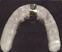 |
| Figure 5. The completed maxillary anterior guided orthosis (MAGO) orthotic after adjustments showing incisive/surtrusive and canine guidance medial surtrusive pathways and cuspal contacts. | Figure 6. Size 0.003 tin foil shims (Buffalo Dental) placed on the MAGO. |
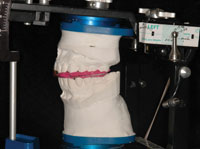 |
| Figure 7. The axis position indicator instrumentation. |
 |
 |
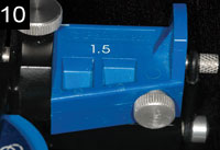 |
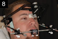
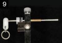
| Figures 8 to 10. Instrumentation for the hinge axis location. The condylar pathway is traced using the Panadent axis path recorder. The Bennett movements are recorded at 1.5 mm, right and left sides. Bennett analogs (1.5 mm) set on articulator, right and left sides. |
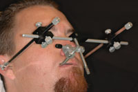 |
| Figure 11. Location of the hinge-axis. Reference pins are set at the hinge axis for a hinge axis transfer to the articulator. |
According to the principles of Bioesthetic Dentistry, the MAGO created an orthopedically stable condylar position,1 with the dentition having equal intensity contacts in closure, an anterior guidance that relegated incisive/surtrusive movement to the central incisors and excursive right and left medial/surtrusion movements to the canines, without any posterior CR contacts away from centric closure.
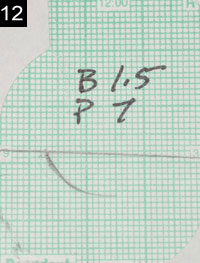
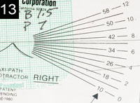
After the joint stabilized, the Panadent axis path recorder was used to locate the hinge axis and to measure the condylar angle and Bennett movements (Figures 8 to 14). A new stone model of the maxillary arch was fabricated and transferred to the Panadent articulator, utilizing a Panadent hinge-bow and maxillary mounting stand (Figure 15). This procedure aligned the patient’s axis of rotation with the hinge of the articulator.
 |
 |
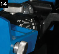 |
| Figures 12 to 14. Right condylar pathway tracing. The condylar angles are measured with the Panadent protractor and set on the articulator. |
A new mandibular model was then mounted, using a new open bite centric-related registration (Figure 16). The condylar angle was measured, using the condylar tracing and a Panadent protractor, then set on the articulator, along with the Bennett movement (by attaching the appropriate Panadent Bennett analogs) (Figures 8 and 14). With this information, all the necessary data to arrive at a final occlusal diagnosis was available. These models were used to plan the final coronaplasty.
EXTRAORAL CORONAPLASTY: CORONAPLASTY CONSIDERATIONS
Prior to proceeding with the occlusal treatment plan on the axis-mounted SCP models, the clinician must be aware that there are times when subtractive coronaplasty procedures alone fail to ideally restore anterior guidance or natural tooth form. In these cases, restorative procedures, performed by a restorative dentist, may be required to complete the case. During that process, the clinician must continually consider these questions:
- What are the likely consequences of each option?
- Which of the consequences can the clinician and the patient accept?
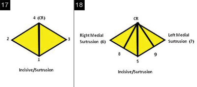
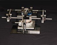
By performing the coronaplasty on the CR mounted models, the practitioner can become truly familiar with the case and help to guide patients through their choices. Before touching the model teeth, the clinician should visualize the envelope of functional motion as a 3-x-3-mm horizontal rhomboid-shaped figure, with the bisection of lines representing the test positions (Figures 17 and 18) at which the clinician will evaluate the clearance of the posterior teeth when the mandible is at that position: (1) incisive test position, (2) left lateral test position, (3) right lateral test position, and (4) CR test position—to observe impediments to closure and function and the deficiency of anterior coupling and guidance (Figure 17). These positions also represent the points of adjustments (adjustment positions) to the teeth at CR (4), incisive adjustment position and pathway (5), right and left lateral adjustment positions border pathways (6 and 7), and the adjustments at the intermediate pathways (8 and 9) (Figure 18). Following the evaluation of the CR discrepancy at test position 4, the actual adjustments to the posterior teeth begin at the first CR contact, in order to harmonize the intercuspal position, with the CR position of the TMJs. Certain protocols or rules are adhered to during the development of the CR contacts.
 |
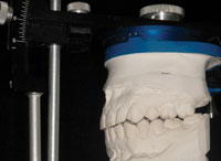 |
| Figure 15. Axis mounted maxillary cast. | Figure 16. With an open-bite centric relation record, the models are mounted in stable centric on the hinge axis. Final diagnosis and treatment plan can now be established. |
|
|
| Figures 17 and 18. Envelope of functional motion. |
After determining the MIP stop point at the adjustment position 4, subsequent additive (addition of wax) and subtractive procedures are performed on the incisors and canines (positions 5 to 9) to finalize the incisive/surtrusion, right and left canine medial/surtrusion guidance, and intermediate pathways, and the anterior guidance, along with any special considerations.
The goal of a coronaplasty is to create the form of the teeth and a proprioceptive anterior guidance to permit incisive and eccentric functional movements of the teeth within this small space, without neuromuscular disharmony. When the teeth do contact (only in swallowing),2 final closure position should be with equal intensity. There should be at least one small point of contact on each cusp tip where the convexity of the cusp tip touches the opposing convexity of the marginal ridge. At this point of closure, the TMJs are guided back into the CR position, thereby in harmony with the contact of the teeth (MIP).
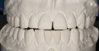
In evaluating the clearance of the posterior teeth at the extent of border movements (test positions 1 to 4), the mandibular model is placed first in the incisive test position with the incisal edges end-to-end (test position 1) (Figure 19). At this position, the posterior teeth should have a clearance of ideally 3 mm at the second molars. In incisive/surtrusive guidance, it is important to see that the contacts of the incisal edges are simultaneous for both maxillary central incisors, and that the maxillary and mandibular midlines are lined up. If there is inadequate space, 2 choices are available: (1) reduce the posterior teeth, or (2) add to the length of the incisors to create more vertical overlap. On the models, this can be accomplished by adding wax (additive coronaplasty) to the incisal edges.
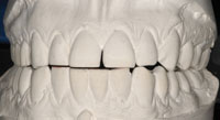
To evaluate the adequacy of the lengths of the canines and their effect on the posterior clearance in both sides (chewing and nonchewing), place the tip of the mandibular canine against the tip of the maxillary canine at test position 2 (left lateral) and again at test position 3 (right lateral). There should be 2 mm of clearance on the chewing side and 3 mm on the nonchewing side at the second molars (Figure 20). Again, the options here are to reduce the height of the posterior teeth or increase the length of the canines. Remember, it is not enough to create just the minimal “clearance” of the posterior teeth. Without adequate space, the posterior teeth can still contact during flexure of the mandible when chewing a hard bolus of food. These contacts become interferences to smooth function.
Do not sacrifice natural tooth length of the posterior teeth before first considering the lengths of the canines and incisors. Increasing their lengths will create greater posterior separation. However, the lengths of the anterior teeth must be evaluated in consideration of the esthetic appearance of the smile and the face. The length of the maxillary canines and central incisors should be evaluated together, and their incisal edges should be level with the horizontal plane.
 |
 |
| Figure 19. Posterior interferences in incisive/surtrusive guidance. |
Figure 20. Inadequate right canine medial/surtrusion guidance results in nonchewing side interferences on the second molars and chewing side interferences on the first bicuspid. |
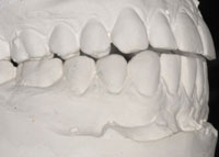 |
| Figure 21. Anterior open bite due to centric interferences to closure at the second molars. |
 |
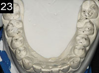 |
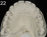
| Figures 22 and 23. Coronaplasty completed on maxillary and mandibular hinge-axis mounted models. There should be at least one small point of contact on each cusp tip where the convexity of the cusp tip touches the opposing convexity of the marginal ridge (Class I occlusion) or fosse (Class II occlusion). |
Preserving and recreating natural biologic form as advocated in Bioesthetic coronaplasty always begins with developing the CR contacts first before developing the additive procedures. At test position 4 (CR), with the articulator locked, the space between the anterior teeth is evaluated as to how much the posterior teeth would have to be reduced in order to get the anterior teeth to couple (Figure 21). The ratio between the second molar and anterior teeth is approximately 1:2.5. In other words, to close an opening of 2.5 mm between the anterior teeth CR contacts, a reduction of approximately 0.5 mm from the maxillary second molar and 0.5 mm from the mandibular second molar (a total of 1.0 mm) is required. If they are, in fact, the primary causes of the anterior CR open bite, fewer adjustments on the first molars and premolars would be required. If the anterior open bite exceeds 2 mm, too much tooth structure would have to be removed from the second molars. In that case, the option of additive restorative considerations would have to be made. With more excessive anterior open bites, orthodontic or surgical intervention may be necessary.
DISCUSSION
Adjustment Considerations for Centric Relation Tooth Contacts
At test position 4, where the actual tooth adjustments begin at the first CR contact, the centric latch of the articulator is closed, and the CR adjustments are made on the models. These centric holding contacts stabilize the mandible and place chewing forces in the long axis of the teeth. Therefore, these centric holding contacts are most important, and care should be taken to preserve them throughout the coronaplasty procedure.3 Strips of black Mylar ribbon are used to mark the initial points of occlusal contact. Optimal preservation of tooth structure, re-creation, and improvement of tooth anatomy are performed, with rules of adjustment protocols in mind.
Rule No. 1: Arc of Closure (Mesial/Distal Adjustments)—Use the mesial uppers distal lowers rule in adjusting anterior/posterior (mesial/distal) relations; ie, adjust the mesial inclines of the upper teeth (mesial uppers) and the distal inclines of the lower (distal lowers) teeth.4,5
Rule No. 2: Line of Closure (Buccal and Lingual Adjustments)—The buccal and lingual adjustments are performed on the lingual inclines of maxillary teeth and the buccal inclines of the mandibular teeth, if the teeth are deflected towards the tongue during closure.
The buccal inclines of maxillary teeth and the lingual inclines of mandibular teeth are adjusted when the teeth are deflected towards the cheek upon closure. Ideally, there should be no contacts on the slopes of cusps when the case is completed.4,5
Rule No. 3: Rule of Thirds—Do not attempt to adjust teeth that have more than 1.0 mm buccal-lingual discrepancy. If a tooth is significantly out of alignment in one arch, and the opposing teeth are positioned in good arch form, reduce the cusps of the malpositioned tooth and place a restoration later (do not recontour the opposing tooth that is in good arch form). If the buccal-lingual discrepancy is greater than one mm, consider orthodontic treatment. If the discrepancy is greater than 2 mm, orthognathic surgery may be necessary to reposition the arches.
Rule No. 4: Adjustments on the Teeth—When the markings of the Mylar ribbons occur on marginal ridges, cut grooves in the ridges and split the contact into 2 spots. Recreate sharp efficient anatomy by:
- Deepening fossae and developmental grooves.
- Deepening and/or creating supplemental grooves on inclines and marginal ridges.
- “Shaving” contact on axial contours of teeth (buccal of lowers, lingual of uppers).
- Do not grind cusp tips!
All the above adjustments should fall within the dictates of normal tooth morphology (Figures 22 and 23).
Adjustment Considerations for Incisive Position and Anterior Guidance
The CR adjustments should stop before mutilating the posterior teeth or encroaching on the necessary anterior space needed for proper anterior vertical and horizontal overlap. Continuing until complete, anterior closure would affect not only the function of the anterior guidance but also the display of the incisal edges and lip support. If it is necessary to leave an anterior open bite in order to have space to add length to the maxillary and mandibular anterior teeth, add wax to the maxillary anterior lingual surfaces and/or the mandibular incisal edges to complete the CR contacts.
After the anterior and posterior contacts are in harmony with the CR position of the joints, an anterior guide system still has to be developed to protect the posterior teeth during function. Unlocking the articulator and using red Mylar ribbon, an incisive pathway (adjustment position 5) is refined by adding wax, if necessary, to the linguals of the central incisors until a smooth recording of the mandibular incisors is made against the mesial marginal ridges of each incisor.
With the incisive adjustments completed, adjustments are then made at the right and left lateral border movements, ie, adjustment positions 6 and 7. Unlock the articulator and place the red marking ribbon between the posterior teeth on both sides. Move the articulator in border movements along the curved Bennett path of the articulator to mark any chewing and nonchewing side interferences. If marks are created, a decision must be made whether to remove the interferences (by reshaping the teeth) or to add wax to the lingual surface of the contralateral maxillary canine to overcome the interference. (Note: Tightening the overlap of the canines rather than reducing the posterior tooth morphology is preferred.) The distal surfaces of the maxillary teeth and the mesial surfaces of the mandibular teeth (distal of uppers, mesial of lowers) are adjusted to remove marks that occur on the cusp slopes. While adjusting lateral movements, do not remove any black CR holding contacts.
After completely removing interferences in the lateral border movements, eliminate all remaining interferences in the intermediate lateral movements (adjustment positions 8 and 9). These will usually show up on the slopes of the cusps.
If the coronaplasty has been completed correctly, the following criteria will have been met:
- Centric contacts of the anterior teeth and posterior teeth will hold 8-µm Mylar ribbon.
- When the casts are moved in the incisive direction, maintaining constant contact with the maxillary and mandibular incisors, an immediate posterior release of the ribbon will occur.
- When the articulator is moved from CR in lateral border paths along the curved Bennett paths, while maintaining contact with the maxillary and mandibular canines, there will be immediate release of the marking ribbon on both the chewing and the nonchewing sides.
The purpose of the adjustments on the stone models is to have the ability to visualize how the coronaplasty will be performed intraorally.
CONCLUSION
This article has presented the treatment planning, clinical and dental laboratory procedures, coronaplasty considerations, adjustment considerations for CR tooth contacts, incisive/ surtrusive positions, and right and left medial surtrusive guidance. The next and final article in this series will discuss the application of the coronaplasty procedures on the patient models, mounted in a SCP, and the transfer of the biologic form and function to the patient.
References
- Okeson JP. Management of Temporomandibular Disorders and Occlusion. 6th ed. St. Louis, MO: Mosby Elsevier; 2008.
- Gibbs CH, Lundeen HC; University of Florida College of Dentistry. Introduction to human chewing [videotape]. Gainesville, FL: Learning Resources & Communications Television Division, University of Florida College of Dentistry; 1986.
- McNeill C. Science and Practice of Occlusion. Chicago IL: Quintessence Publishing; 1997.
- Dawson PE. Evaluation, Diagnosis, and Treatment of Occlusal Problems. St. Louis, MO: Mosby; 1974.
- Dawson PE. A classification system for occlusions that relates maximal intercuspation to the position and condition of the temporomandibular joints. J Prosthet Dent. 1996;75:60-66.
Dr. Hunt is a graduate of Fairleigh Dickinson University Dental School and maintains a private practice in Brea, Calif. He can be contacted at kenhunt@surfside.net.
Disclosure: Dr. Hunt reports no disclosures.
Dr. Turk is a graduate of the University of Southern California Dental School and maintains a private practice in Orange, Calif. He can be contacted via the e-mail address gmturk@mouthdoc.com.
Disclosure: Dr. Turk reports no disclosures.

