
INTRODUCTION
Dental implants for replacing missing teeth have become an integral part of current conventional dentistry. Accepted protocols now include 2-stage delayed loading; one-stage delayed loading; immediate loading in a healed receptor site; the use of tilted implant placement; immediate loading in fresh extraction sites; and partial extraction therapy (PET), the socket shield technique (SST), or the root membrane (RM) concept. Technology has provided clinicians with enhanced tools for diagnosis and treatment planning, instrumentation for surgical intervention, improved implant surface treatments and thread design, improved abutment-to-implant connections, sophisticated dental laboratory software and CAD/CAM applications, a greater selection of transitional and definitive restorative materials, static and dynamic navigation, and changes in drill designs and drilling protocols. Dental implant procedures are predictable, effective, and essential to address the needs of patients.
In their various formulations, partial extraction procedures have been demonstrated to be proven methodologies to preserve bone and soft-tissue volume.1-7 Our 2017 Dentistry Today article reviewed 3-D diagnostic tools for planning and executing RM/PET procedures based on the “Triangle of Bone” concept and specific instrumentation to achieve successful outcomes.5 The ability to do these procedures requires careful diagnosis, treatment planning, and excellent control of the drilling process to ensure that the root fragment will be maintained while maximizing implant stability. In many cases, it may also be possible to provide an immediate transitional restoration when high implant stability is achieved. However, complications can also arise when the root fragment is lost or the implant fails to integrate. It should be noted that PET has mainly been accomplished with a “diagnostic free-hand” method for sectioning roots, osteotomy preparations, and implant placement. This article describes methods for providing PET procedures using “full-template guidance” based on a thorough appreciation of the existing anatomic structures utilizing advanced, state-of-the-art treatment planning tools, 3-D design software, 3-D printing, and/or CAD/CAM surgical templates.
One indication for considering PET is when a patient presents with a horizontally fractured clinical crown (Figure 1). While a 2-D radiograph will reveal the extent of the horizontal fracture, length of the remaining root, and approximation of the bone apical to the root, there is not enough information to plan for a PET procedure. A CBCT scan is recommended to fully appreciate the root position within the alveolus, and the potential difference between the trajectory of the bone and the trajectory of the root as can be visualized with a cross-sectional image (Figure 2). Utilizing interactive treatment planning software makes it possible to plan the initial drill path to accurately section the root to its apex (Figure 3a). This can be accomplished by creating a custom implant design to match the diameter of the initial drill with an abutment projection to fully appreciate the trajectory through the clinical crown (BlueSky Plan [Blue Sky Bio]). It is important to visualize the root fragment that will remain to properly simulate the position of the implant in the alveolus (Figure 3b). The apical portion of the implant can be positioned to gain stability in host bone using the Triangle of Bone concept. It is important to note that a cross-sectional slice may only be 0.125 mm in thickness based on the CBCT acquisition, and therefore, all images in all views must be visualized to confirm the plan. Utilizing 3-D segmentation (separating objects by density values), it is possible to define each root and further assess the simulated position of the implant with a sagittal cut throught the 3-D reconstructed volume (Figure 4).
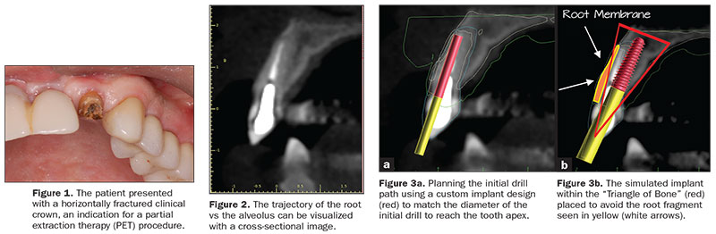 |
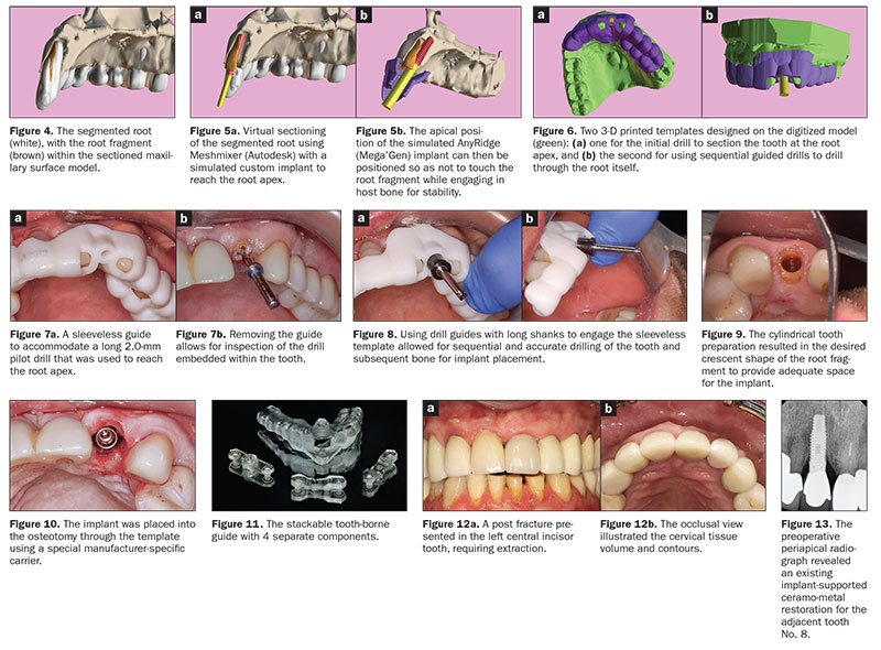
The ability to export volumes in a standard triangulation language (STL) format allows these objects to be edited and utilized in other software applications, such as Autodesk’s Meshmixer. The STL file of the root was imported into Meshmixer, and the root was virtually sectioned using “Boolean difference” to mimic the crescent shape for PET (Figure 5a). The apical position of the simulated implant can then be positioned so as not to touch the root fragment while engaging in host bone for stability (Figure 5b). Planning with such precision is predicated on the acquisition of a satisfactory CBCT scan with a proper field of view and the incorporation of occlusal surface data STL files of the arch form digitized through either a desktop scanner or an intraoral scan imported into the software. Two 3-D printed templates were then designed on the accurate digitized surface model: one for the initial drill to section the tooth at the root apex, and the second for sequential guided drills to drill through the root itself (Figure 6). The tooth-borne surgical guide utilized a sleevelessguided approach requiring a 2.0-mm pilot drill long enough to reach the root apex. (Figure 7a). Removing the guide allows for inspection of the drill through the tooth (Figure 7b). Using guided drills with long shanks in a sleeveless guide allowed for sequential and accurate removal of tooth structure and subsequent bone beyond the apex of the natural tooth root (R2Gate [Mega’Gen]) (Figure 8). The cylindrical tooth preparation/osteotomy resulted in the desired crescent shape to provide space for the implant (Figure 9). The root was then sectioned mesial-distally using specialized drills (Root Membrane Kit [Mega’Gen]), and the palatal section of the root was removed. Utilizing the template, the implant is placed into the osteotomy using the correct implant carrier to achieve “full-template” guidance and stability measured with resonance frequency analysis (RFA)/implant stability quotient (ISQ) (Figure 10). The concept of drilling through the root is not new and has been reported in the literature.8 The implementation of guided methods for the SST has also been reported using a CAD/CAM fabricated template.9 However, the ability to use technology to plan and execute a fully guided procedure for a PET, an SST, or an RM technique illustrates an additional methodology to aid clinicians in successful outcomes.
The first concept described the use of 2 separate templates: one for separating the root at the apex, and the second to drill through the tooth and place the implant. Continuing the discussion, we present a second option that does not require the removal of the base template but has inserts to allow for the different drills and angulation required for the PET technique: the Stackable Tooth-Borne Guide (STBG). This new technique has 4 separate components: (1) the base template (the STBG), (2) a pilot drill guide for the root apex (APEX STACK), (3) a crescent-shaped guide for shaping root fragments (PET Shaper STACK), and (4) a guide for osteotomy drilling and placing the implant through the guide (Surgical Guide STACK) (Figure 11).
 |
CASE REPORT
A 62-year-o
ld male presented with a hopeless prognosis for a post fracture in his left central incisor tooth, requiring extraction (Figure 12a). The occlusal view illustrated the cervical tissue volume and contours (Figure 12b). The preoperative periapical radiograph revealed an existing implant supporting the ceramo-metal restoration for the adjacent tooth No. 8 (Figure 13). The CBCT scan (CS 9600 [Carestream Dental]) cross-sectional image revealed a favorable pre-op condition—relating to the trajectory of the endodontically treated root to the alveolus—for a PET procedure (Figure 14a). Using the native Carestream CS 3-D Imaging Software, (Carestream Dental), a simulated implant and an abutment projection (yellow outline) were positioned within the available bone to avoid the root fragment (Figure 14b). The final positioning of the implant, as determined by the restorative requirements, design, and fabrication of the tooth-borne stackable surgical templates, was accomplished using dedicated interactive treatment planning software (360DPS Imaging). The base template was designed to seat firmly on the adjacent teeth, incorporating buccal and lingual hexagonal offsets to engage the different drill-guide inserts (Figure 15a). Separate inserts were then fabricated for the initial drill guide to reach the root apex to accommodate sectioning, followed by a second guide for final osteotomy drilling and implant placement (Figures 15b and 15c). The accuracy of the implant and template design phase provides the opportunity for true restoratively driven planning, which can then be combined with CAD/CAM applications to also design and fabricate a patient-specific abutment and transitional restoration in advance of a surgical intervention (Figure 16).
Prior to the guided drilling, a Gates-Glidden drill was used to remove any gutta-percha within the root. Utilizing the tooth-borne template and the first insert, initial long shaper drills were used (IS1, IS2) to reach the apex of the root (Root Membrane Kit) (Figure 17). A periapical radiograph confirmed that the apex length was reached and that all gutta-percha was removed (Figure 18).
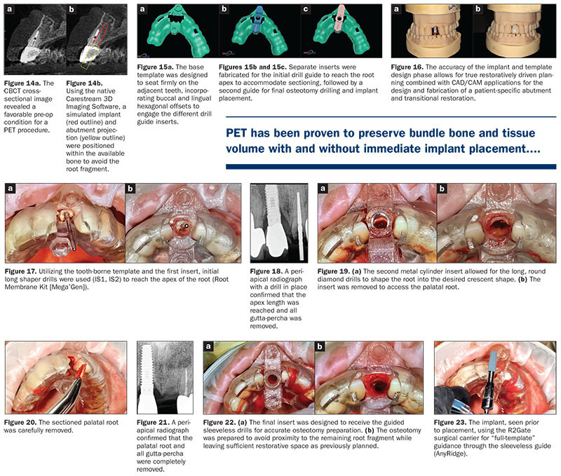 |
The second insert has a metal cylinder that allows for long, round diamond drills to shape the root into the desired crescent shape (Figure 19a). The insert was removed to access the palatal root (Figure 19b). Using appropriate instrumentation (such as periotomes, Elvatomes, or FRINGS Forceps [TBS Dental]), the palatal root was carefully removed (Figure 20). A periapical radiograph confirmed that the palatal root was completely removed (Figure 21).
The next insert contained the final diameter to receive the guided, sleeveless drills for the osteotomy preparation (Figure 22a). The osteotomy was prepared to avoid proximity to the remaining root fragment while leaving sufficient restorative space as previously planned in the software simulation (Figure 22b). Implant placement was facilitated by the R2Gate surgical carrier for “full-template” guidance at the appropriate torque values (AnyRidge [Mega’Gen]) (Figure 23). Depth control and rotational positioning were accurately confirmed with the “notch” indicated on the template to correspond with the insertion tool (Figure 24a). The occlusal view illustrates that the anti-rotational internal conical-hex connection was positioned toward the facial (Figure 24b).
The initial plan was for immediate extraction, immediate placement, and immediate restoration. Therefore, it was essential to measure the implant’s stability with an objective technology: RFA, which provides an ISQ utilizing an implant-specific SmartPeg (Osstell) and Mega ISQ [Mega’Gen]). The baseline ISQ value (76) confirmed sufficient initial stability to place an immediate restoration (Figure 25). The prefabricated CAD/CAM abutment was then secured to the implant, and a postoperative periapical radiograph confirmed successful subcrestal placement for this platform-switch design (Figure 26a). The transitional acrylic restoration was then placed and examined for any occlusal interferences (Figure 26b). It was important that the restoration be out of occlusion to avoid premature forces that could complicate integration. The soft-tissue contours were excellent, and no sutures were required since no flap was raised (Figures 26c and 26d).
After a period of 8 weeks, the implant stability was measured to be at 80 ISQ, confirming that the integration process had continued to progress successfully and was ready for the definitive restoration. An intraoral scanner and scanning abutment were then utilized to capture the position of the implant and soft-tissue emergence profile. A post-op CBCT scan revealed the intact crescent shape of the root membrane, as seen in Figure 27a and outlined in red in Figure 27b, facial to the opaque implant. The post-op cross-sectional view clearly illustrates the position of the implant (Figure 28a) with the definitive restoration located palatal to the root membrane, as outlined in yellow in Figure 28b.
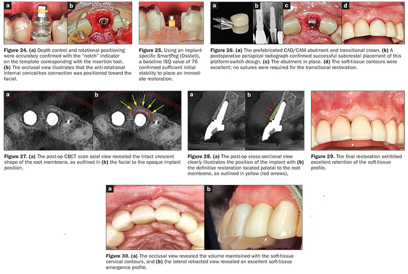 |
The final restoration was then delivered and exhibited excellent retention of the soft-tissue profile (Figure 29). The occlusal view revealed the cervical contours of the soft tissue (Figure 30a), and the lateral retracted view revealed excellent soft-tissue emergence profile and volume (Figure 30b).
IN SUMMARY
PET, RM, and socket shield concepts have gained popularity as these techniques have been refined and have proven efficacy with the publication of long-term studies. The purpose of retaining the root is to maintain the periodontal ligament attachment to the bony walls of the socket to prevent subsequent resorption and loss of tissue volume, which often occurs after tooth extraction. PET has been proven to preserve bundle bone and tissue volume with and without immediate implant placement, yet this minimally invasive treatment modality is highly technique sensitive and may result in complications if proper protocols are not followed. Therefore, a complete understanding of the 3-D anatomic presentation is essential for preliminary diagnosis, treatment planning, and execution of the procedure.
This article described 2 alternatives that maximize the diagnostic phase using state-of-the-art CBCT imaging and planning software to provide full-template guidance with a new STBG with specific inserts for the root preparation as well as the osteotomy preparation and delivery of the implant. As with most techniques, further clinical trials are recommended to provide additional long-term data to validate these treatment modalities.F
Acknowledgments:
The authors would like to thank Dr. Barry Kaplan, Morristown, NJ, and Ahmed Khater of 360 Imaging, for their expertise and assistance in the preparation of this article.
References
- Hürzeler MB, Zuhr O, Schupbach P, et al. The socket-shield technique: a proof-of-principle report. J Clin Periodontol. 2010;37:855-862.
- Siormpas KD, Mitsias ME, Kontsiotou-Siormpa E, et al. Immediate implant placement in the esthetic zone utilizing the “root-membrane” technique: clinical results up to 5 years postloading. Int J Oral Maxillofac Implants. 2014;29:1397-1405.
- Bäumer D, Zuhr O, Rebele S, et al. The socket-shield technique: first histological, clinical, and volumetrical observations after separation of the buccal tooth segment—a pilot study. Clin Implant Dent Relat Res. 2015;17:71-82.
- Bäumer D, Zuhr O, Rebele S, et al. Socket shield technique for immediate i
mplant placement—clinical, radiographic and volumetric data after 5 years. Clin Oral Implants Res. 2017;28:1450-1458. - Ganz SD, Tawil I, Mitsias ME. The root membrane concept: in the zone with the “triangle of bone.” Dent Today. 2017;36:80-84.
- Gluckman H, Salama M, Du Toit J. A retrospective evaluation of 128 socket-shield cases in the esthetic zone and posterior sites: partial extraction therapy with up to 4 years follow-up. Clin Implant Dent Relat Res. 2018;20:122-129.
- Siormpas KD, Mitsias ME, Kotsakis GA, et al. The root membrane technique: a retrospective clinical study with up to 10 years of follow-up. Implant Dent. 2018;27:564-574.
- Rodriguez-Tizcareño MH, Bravo-Flores C. Anatomically guided implant site preparation technique at molar sites. Implant Dent. 2009;18:393-401.
- Saeidi Pour R, Zuhr O, Hürzeler M, et al. Clinical benefits of the immediate implant socket shield technique. J Esthet Restor Dent. 2017;29:93-101.
Dr. Ganz received his specialty certificate in maxillofacial prosthetics/prosthodontics, which led to a focus on the surgical and restorative phases of implant dentistry and his contributions to 15 implant-related textbooks and over 120 articles in the dental literature. He is a Fellow of the Academy of Osseointegration, a Diplomate of the International Congress of Oral Implantologists (ICOI), US ambassador and president of the Digital Dental Society, and co-director of Advanced Implant Education (AIE). Dr. Ganz is on the faculty of the Rutgers School of Dental Medicine and maintains a private practice in Fort Lee, NJ. He can be reached via email at drganz@drganz.com.
Dr. Tawil received his DDS degree from the New York University College of Dentistry and has a Master’s degree in biology from Long Island University. He is co-director of AIE. He is a Diplomate of the International Academy of Dental Implantology as well as a Fellow of the ICOI and the Advanced Implant Academy.He also received recognition for outstanding achievement in dental implants from the Advanced Implant Academy. He maintains a general private practice in Brooklyn, NY, where he focuses on implant therapy. He can be reached via email at tawildental@gmail.com.
Disclosure: The authors report no disclosures.
Related Articles
Digital Technologies: A Roundtable Discussion on Changing the Face of Dentistry

