The overall quality of panoramic radiographs can be greatly improved with greater attention to initial patient selection, preparation, and positioning. The exposure times for panoramic radiographs vary from 12 to 20 seconds. A patient who is unable to sit still or remain still for this amount of time should not be selected to be exposed to this projection. Over the years it has become accepted that the panoramic projection is a generalized radiographic overview of the maxillofacial region, but one lacking adequate resolution and detail. Admittedly, the panoramic projection is technique sensitive, but one that can be easily mastered if the clinician can recognize, identify, and know how to correct the technical errors. Whether the panoramic machine uses conventional films or is digital, the same principles apply.
A major reason that many panoramic (or other) radiographs are not of interpretive quality is a lack of density. There must be sufficient density to enable the investigator to identify the outlines of structures on the radiograph. In the majority of cases a lack of density is because of a lack of a quality assurance program in processing radiographs, but that is not the purpose of this article. Here it is assumed that a correct screen/film combination has been used. Other major problems arise from the preparation and positioning of the patient at the time of the exposure.
 |
|
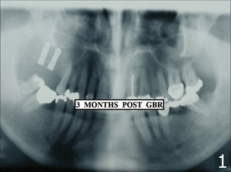
Figure 1. The type of high-quality radiograph that should be consistently obtained in private practice.
|
 |
|
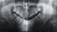
Figure 2. An average shape of a focal trough of a panoramic x-ray machine.
|
PANORAMIC CONCEPTS: FOCAL TROUGH
Panoramic radiography is a form of tomography. In tomography, slices are created by blurring images in front and back of the area of interest through controlled simultaneous movement of the source of radiation and the image receptor. In panoramic radiology the image layer is called the focal trough. The focal trough is a specific, curved volume within which images of structures of the maxillofacial region can be clearly seen on the panoramic radiograph. The basic shape of the focal trough is indicated in Figure 2.
The focal trough for different panoramic machines varies slightly, but the basic shape remains the same. The vertical height of the volume of tissue is limited to the width of the film, and a 6-inch wide film is preferable to a 5-inch film. With the narrower width film, the images of the TMJ area often are not captured. This choice of film size can only be made at the time of the purchase of the machine. The focal trough in the anterior part of the maxillofacial region is much narrower than in the posterior region and thus, it is more critical that the patient is positioned correctly in this area. From Figure 2 it can be seen that the anterior teeth should be positioned in the middle of the focal trough (position 2). If the teeth are placed in position 1, the teeth have been positioned too far forward and in position 3 the teeth are positioned too far back in the focal trough.
The clearest images of the region of interest will appear with the teeth positioned in the middle of the focal trough. As structures progressively are situated more toward the periphery of the focal area they become more and more blurred until they reach a point where the images are not seen at all because of motion blurring. The term fuzzy is often used to describe the poor outline of these images. Thus, the patient must be positioned with the neck straight and symmetrical so that the anterior maxillofacial structures will fall within the optimal region of the focal trough. The focal trough is much wider posteriorly, and thus it is easy to obtain clear images of the posterior teeth and anatomy in this area. The focal trough in the posterior region of the jaws is large and varies between 1 and 1.5 cm. Therefore, the images of posterior teeth are usually clearly seen. From position 4 in Figure 2, it can be seen that posterior teeth can be moved markedly forward or backward, laterally or mesially, and still be well within the focal trough. Thus, when inspecting the diagnostic quality of a panoramic radiograph, the images of the anterior teeth are the areas that must be inspected more critically to determine the technical quality of the radiograph.
Thus, with the incisor teeth placed in position 1 (Figure 2), the outlines of the images of the crowns and the roots, as well as the trabecular bone pattern surrounding these teeth, will be seen most sharply. If the teeth are placed in position 2, the outlines of the images of the crowns of the teeth become narrow and fuzzy. In this position, the teeth are considered as being positioned too far forward in the focal trough and the further forward the narrower and fuzzier the images of the incisor teeth will appear. If the teeth are placed in position 3, they are considered as positioned too far back in the focal trough and the wider the images of the crowns of the teeth will appear. Again, the further back in the trough, the wider they will become.
In some panoramic machines the size of the focal trough can be made smaller or larger to fit the size of the patient. Changing the size of the focal trough to fit the size of the patient is known as creating the profile index for that patient. Newer machines with LED displays will indicate a number that can be recorded for taking future panoramic projections to assure that same position of the patient for future exposures. Alternatively, if the patient is not positioned correctly when the exposure is made, this number can be utilized to assist in positioning the patient in better postero-anterior alignment should another panoramic radiograph be required in the future.
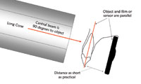
When taking a periapical radiograph, the sizes of the object and the image should be the same. With a well-taken panoramic radiograph, with all the images of the anterior region clearly outlined, there is always a magnification of 15% to 20% in the vertical dimension. When determining the height of the alveolar bone above the mandibular canal in the body of the mandible when planning implant surgery, this magnification must be included in the calculations.
IDENTIFYING THE CAUSES OF THE ERRORS AND MAKING THE CORRECTIONS
When determining the quality of a panoramic radiograph, check whether there are any errors in the vertical or horizontal positioning of the head; whether the patient is positioned symmetrically; and whether there are errors in patient instruction such as not moving during the exposure, not elevating the tongue, or having removed metal objects about the face. The first step is to check whether the smile line is correct.
Horizontal Positioning Errors
When exposing the panoramic radiograph, the patient must be positioned with the incisor teeth in the middle of the focal trough. For dentate patients, a notched bitestick is generally used to position the incisor teeth of both jaws. As mentioned above, positioning the patient only a few millimeters too far forward or backward will greatly affect the position of the incisor teeth in the focal trough and will markedly alter the width of the images of these teeth. It is important to stress that a positioning error of merely 3 to 4 mm can make a dramatic difference to the appearance of the images.
If the patient is positioned too far backward, (Figure 2, position 3) the skin anterior to the tragus can be felt immediately posterior to the head support. The further the patient is positioned backward in the focal trough, the wider the images of the anterior teeth will become until they are so wide that the outlines of the crowns of the teeth can hardly be discerned. In the older machines this is because the patient is positioned so that the skin anterior to the tragus can be seen or felt. In the newer machines it is because the vertical beam of light is positioned on a tooth anterior to the position recommended by the manufacturer. It is important to check bilaterally that the position of the beam is on the same teeth. Again missing teeth in this region can create a positioning error.
Vertical Positioning Errors
For lack of a better descriptive term, “smile line” is accepted when describing the correct appearance of the images of the occlusal plane of the teeth on the panoramic radiograph. To determine if the smile line is correct, one can draw an imaginary line on the radiograph from the mesial incisal tip of the first maxillary molar tooth on one side to the same point on the contralateral tooth (or on the second molar tooth if the first one is missing). The incisal surface of the maxillary central incisor teeth should appear 0.5 to 0.75 cm inferior to this line. This positioning will prevent the opaque image of the hard palate from being superimposed over the apices of the maxillary anterior and premolar teeth. The more the head is elevated the broader and more opaque the image of the hard palate appears.
If the head/chin position is too high (a lack of negative vertical angulation), the images of the hard palate and the ghost image of the contralateral hard palate superimpose creating a broad horizontal opaque line. This opacity usually lies mainly over the apices of the premolar and anterior teeth preventing visualization of variations from the normal in this region. The smile line will also then not be seen. On the radiograph, the occlusal plane of the teeth will then appear horizontal or, with a positive occlusal plane, as a “frown line.”
If the head/chin position is too low the images of maxillary anterior teeth will appear elongated and the mandibular anterior teeth will appear foreshortened. Also the anatomy of the mandibular midline area will appear blurred. The lower the position of the head, the higher the image of the hyoid bone will appear. This image will superimpose on the mandible.
Because dropping the head increases the vertical height of the image of the face, the TMJs will more likely not be visualized.
In addition, the higher or lower the position of the head away from the ideal vertical angulation, the more the images of the premolar teeth will appear to overlap.
There is one advantage to placing the atient in this position. The maxillary and frontal sinuses can be viewed clearly with the head dropped a little too much. The higher or lower the position of the head in relationship to the smile line, the more the images of the premolar teeth will appear to overlap each other.
Pharyngeal Air Space
The pharyngeal air space can create a horizontal lucency over the images of the maxillary anterior teeth from the second premolar area on one side to the second premolar on the opposite side, thus preventing the visualization of the apices of these teeth. Ideally, no lucency created by the pharyngeal air space should appear over the images of the apices of these teeth.
To avoid the image of the pharyngeal air space, the tongue must be placed against the hard palate “in the swallowing position,” and it must be maintained in that position during the entire exposure. If the technician does not instruct the patient in the swallowing position,patients often double their tongues backward creating an even larger pharyngeal air space and a larger lucency on the resultant radiograph. It is often an advantage initially to ask the patient to feel where the position of the tongue is when swallowing naturally. Many patients only elevate the tongue after having been instructed to do so.
If one looks at the panoramic radiograph (Figure 1) in this area, it can be seen that the tongue was elevated when the right side of the face was exposed; but the tongue was slowly dropped when the left side was exposed, showing the dorsum of the tongue and vague pharyngeal lucency.
Eliminating the Midline Vertical Opacities
In the midline area of the mandible, the images of the teeth should not be obscured by opacities. There are two main causes of vertical triangular midline opacities. The completely opaque artifact is because of the lead apron being placed too high at the back of the neck. When taking a panoramic radiograph, the x-ray tube movement begins on the side of the patient and moves around the back of the patient to the opposite side. Thus, the lead apron is placed on the front of the patient primarily for their emotional comfort. In addition, the beam is very limited in diameter and is directed in an upward direction. Thus, the front of the body of the patient does not require lead shielding.
The less opaque vertical opacity is because of the slumped spine/vertebra when the patient is not positioned with the neck straight. The more the spine is slumped the more opaque this opacity will appear. It is important that the patient is seated/standing completely upright when making the exposure. A patient will often straighten their neck when they are requested to push out their chest.
Some older patients are not able to straighten the cervical spine. If one suspects problems in the midline area of the face in such a patient, it would be preferable to take an occlusal radiograph of this region.
Images of Teeth Appearing Wider on One Side Than the Other
If the patient is not positioned symmetrically, the images in the cuspid/premolar region on one side will appear wider than the other side. One can avoid this problem by assuring that the amount of tragus felt immediately posteriorly to the head support bilaterally is the same. In the newer machines this can be avoided by ensuring that the vertical beam is pointing to the same position on the same teeth bilaterally. Where a patient is missing a lateral incisor or a cuspid tooth, this can present a problem. To further assist in positioning the patient, some machines also have a vertical light that should correspond to the mid-sagittal line of the face of the patient.
The head of the condyle will also then appear larger on the one side of the radiograph than the other. Where the images of the premolar teeth bilaterally appear symmetrical in width on the radiograph, the one head of the condyle may actually be larger than the other side and may require further investigation.
Images of Removable Appliances
The patient must be requested to remove removable metal appliances in the oral cavity prior to the exposure of the panoramic radiograph. The technician also must observe whether the patient is wearing eyeglasses, earrings, nose rings, or hair clips at the back of the head and request the patient remove these too. There is no need to remove hair clips on top of the head as they are not in the path of the primary beam. Sometimes a patient is embarrassed to inform the technician that they are wearing removable bridges, and these images will appear on the radiograph. Also, patients sometimes are reluctant or unable to remove tongue rings or earrings. Removal of all such appliances is highly desirable as metallic objects will often result in a large double image on the opposite side of the face or vice versa. Double images are always larger, more poorly demarcated, and positioned in a more superior location on the opposite side of the radiograph.
When patients are wearing complete dentures with no metal clasps or bars, it is advisable to leave the dentures in the mouth as the patient can be positioned better in the focal trough and as the outlines of anatomy and pathology are more clear. Where the teeth are acrylic, nothing will be seen on the radiograph; where the denture has porcelain teeth, these images will be seen between the alveolar ridges but will not interfere with viewing relevant anatomy or pathology.
Viewing the TMJ
When purchasing a panoramic machine it is preferable to buy one that utilizes a film size that has a 6-inch rather than a 5-inch width. With the smaller width, the TMJ more often does not appear on the radiograph. This is particularly true in patients with large faces. Also, the more the face/chin is dropped the greater the vertical distance of the face and the less likely the TMJ will be imaged on a radiograph that is 5 inches wide. In the radiograph in Figure 1, the film is 5 inches wide and the outline of the superior head of the head of the condyles is not seen as completely as one would with a 6-inch wide film.
Also, if the patient is seated too far back in the focal trough, the TMJ area will also move posteriorly and may be out of the focal trough; thus the images will not appear on the radiograph.
CONCLUSION
The more common technical errors for panoramic radiographs and explanations for these errors have been reviewed. Awareness and avoidance of the errors discussed above will improve the quality of panoramic radiographs in clinical practice. In a follow-up article, examples of panoramic radiographs with the errors described here will be shown, and explanations will be given for correcting the problems.
Dr. Serman is professor of oral radiology, Division of Oral and Maxillofacial Surgery, at the School of Dental and Oral Surgery, Columbia University in New York, NY. Dr. Serman is also the American director on the board of directors of the International Association of Dento Maxillo Facial Radiology. At the Scientific Congress of the International Association of Dento Maxillo Facial Radiology (IADMFR), held in Glasgow, Scotland, in 2001. Dr. Serman was elected as a fellow of the IADMFR, the tenth time in the history of the association that this award has been made.
Dr. Horrell is an assistant professor of oral radiology, Division of Oral and Maxillofacial Surgery, at the School of Dental and Oral Surgery, Columbia University in New York, NY.
Dr. Singer is an associate professor in the Division of Oral and Maxillofacial Radiology, University of Medicine and Dentistry of New Jersey, in Newark, NJ.