
The overall quality of panoramic radiographs can be greatly improved when particular attention is paid to initial patient preparation and positioning. This will result in higher diagnostic yields that in turn will result in better patient management and treatment. In this article we show examples of the more common technical errors that often occur when taking panoramic radiographs and explain how these errors can be avoided and/or corrected. This will allow the clinician or technician to improve the quality of panoramic radiographs. Whether the panoramic machine uses conventional films or is digital, the same principles apply.
When taking a periapical radiograph, the size of the object and the image should ideally be the same. On a correctly taken panoramic radiograph with the patient correctly positioned, and with all the images of the anterior region clearly outlined, there is always a magnification of 15% to 20% in the vertical dimension. Thus, when determining the height of the alveolar bone above the mandibular canal in the body of the mandible during the planning of implant surgery, this magnification must be included in the calculations. This also applies to measuring the amount of alveolar tooth support. If requested, several panoramic machine companies will supply a ruler that takes this magnification into consideration. However, in the horizontal plane, particularly in the anterior region of the mouth, there can be magnification or demagnification, depending on the horizontal positioning of the patient.
For older machines the correct patient position in the horizontal plane is such that the whole of the tragus (the prominence anterior to the external opening of the ear) must be able to be felt immediately behind the head support. If the whole of the tragus cannot be felt, the patient is seated too far forward. If the skin anterior to the tragus can also be felt, the patient is seated too far back.
Several panoramic radiographs shown have been cropped so that the technical errors can be visualized more clearly.
NARROW, “FUZZY,” ANTERIOR TEETH (FIGURES 1, 2, 3, AND 6)
When exposing a panoramic radiograph, the patient must be positioned with the incisor teeth in the middle of the focal trough. Fuzzy images of the incisor teeth will appear when the patient is seated too far forward in the focal trough. It is important to stress that a positioning error of only 3 to 4 mm in the horizontal plane can make a dramatic difference to the width of the images. In these cases, interproximal caries may not appear or may appear much smaller. The appearance of periapical pathology may be similarly affected.
To avoid this problem with older units, one should check that the correct amount of tragus is felt bilaterally; on newer machines the correct patient position is assured by the vertical indication beams positioned on anterior teeth. Missing teeth in this region may make it difficult to correctly position the patient (Figure 2).
BROAD ANTERIOR TEETH (FIGURE 2)
If the patient is positioned too far back (posteriorly), the skin anterior to the tragus can be felt immediately posterior to the head support. The further back the patient is positioned in the focal trough, the progressively wider the images of the anterior teeth will become until they are so wide that the outlines of the crowns of the teeth cannot be discerned.
To correct the problem when using older machines, the patient must be positioned further forward so the operator does not feel the skin anterior to the tragus. In the newer machines this problem occurs because the vertical beam of light is positioned on a tooth anterior to the position recommended by the manufacturer. It is important to check on both sides that the position of the beam is on the same teeth. Again, missing teeth in this region can create a positioning error. Because of this distortion periapical pathology may not be visible.
ELONGATED MAXILLARY ANTERIOR TEETH AND FORESHORTENED MANDIBULAR ANTERIOR TEETH (FIGURE 1)
For lack of a better descriptive term, “smile line” is accepted when describing the correct horizontal appearance of the images of the occlusal plane of all the teeth on the panoramic radiograph. If the head/chin is positioned too low, the images of the maxillary anterior teeth will appear elongated and the mandibular anterior teeth will appear foreshortened. Also, the anatomy of the mandibular midline area will appear blurred. This is also because, when the chin is dropped, it goes down but also backward, and out of the focal trough. The lower the position of the head, the higher the images of the hyoid bone will appear. This may superimpose on the mandible or the apices of the mandibular premolar or first molar teeth. Because dropping the head increases the vertical height of the image of the face, the TMJ may not be visualized. To avoid this problem the operator must check that the ala of the nose is positioned only slightly inferior to the height of the tragus (Figure 3).
BROAD, HORIZONTAL OPACITY OVER THE MAXILLARY ANTERIOR TEETH (FIGURES 3 AND 4)
If the head/chin position is too high (a lack of negative vertical angulation), the images of the hard palate and the ghost image of the contralateral hard palate superimpose creating a broad, horizontal opaque line. This opacity usually lies mainly over the apices of the maxillary anterior and premolar teeth, thus preventing visualization of variations from the norm in this region. On the radiograph, the images of the occlusal plane of the teeth will then appear horizontal or, with a positive occlusal plane, as a “frown line.” The higher the chin is raised, the broader the opacity and more likely the opacity will superimpose on the apices of the anterior and premolar teeth. Also, the more the chin is elevated, the lower the opacity will appear and will obstruct more of the apical area of the anterior teeth. In addition, the higher or lower the position of the head away from the ideal vertical angulation, the more the images of the premolar teeth will appear to overlap. The problem here is the ala of the nose was positioned higher than the tragus. To avoid this problem the operator must check that the ala of the nose is positioned only slightly inferior to the height of the tragus (Figure 4).
HORIZONTAL LUCENCY OVER THE MAXILLARY ANTERIOR TEETH (FIGURES 4, 5, AND 7)
The pharyngeal air space creates a horizontal lucency over the images of the apices of the maxillary anterior teeth from the second premolar area on one side to the second premolar on the opposite side, thus preventing the visualization of the apices of these teeth and obscuring pathology. In Figure 4, the lucency extends from the second molar on one side to the second molar on the opposite side.
Ideally, no lucency created by the pharyngeal air space should appear over the images of the apices of the maxillary anterior teeth. To avoid the image of the pharyngeal air space, the tongue must be placed against the hard palate in the swallowing position and it must be maintained in that position during the entire exposure. If the technician does not instruct the patient “in the swallowing position,” patients often will double the tongue backward creating an even larger pharyngeal air space and a larger lucency on the resultant radiograph. To avoid the problem, instruct the patient to maintain/elevate the tongue against the hard palate, in the swallowing position, for the duration of the exposure (Figure 5).
MIDLINE VERTICAL OPACITIES (FIGURES 2, 4, 5, AND 6)
In the midline area of the mandible, the images of the teeth should not be obscured by opacities. There are two main causes of vertical triangular midline opacities. The completely opaque artifact is because of the lead apron being placed too high at the back of the neck.
The less opaque vertical opacity is because of the slumped
spine/vertebra (Figures 2, 4, and 6) when the patient is not positioned with the neck straight. It is important that the patient is seated/standing with the neck completely upright when making the exposure. A patient will often straighten their neck only when they are requested to push forward or to push out their chest.
If the neck is bent only slightly, the midline opacity will not be marked and the images of the mandibular anterior teeth in this region will still be seen. The more the spine is slumped, the more opaque this will appear.
To avoid this problem, check that the neck is straight at all times. With older patients who are unable to straighten the neck, an occlusal projection of the mandibular region may be needed for a greater diagnostic yield.
IMAGES OF TEETHAPPEARING WIDER ON ONE SIDE THAN THE OTHER (FIGURE 2)
If the patient is not positioned symmetrically, the images in the cuspid/premolar region on one side will appear wider than the other side. One can avoid this problem by checking that the amount of tragus felt immediately posteriorly to the head support bilaterally is the same. In the newer machines this can be avoided by checking that the vertical beam is pointing to the same position on the same teeth bilaterally. Where a patient is missing a lateral incisor or a cuspid tooth, this can present a problem with the newer machines. To further assist in positioning the patient, some machines also have a vertical light that should correspond to the mid-sagittal plane of the patient’s face.
The head of the condyle may also then appear larger on one side of the radiograph than the other. If the teeth bilaterally are the same size but the head of the condyle on one side is much larger, further investigation is warranted. To avoid the problem, check that the patient is positioned symmetrically.
By applying this principle to an image of an impacted tooth that appears broader mesio-distally than the contralateral tooth or the adjacent teeth, it can be concluded that this tooth is positioned lingually/palatally to the adjacent teeth in the arch (Figures 6 and 7).
IMAGES OF REMOVABLE OBJECTS AND APPLIANCES (FIGURES 2, 6, AND 7)
All patients must be requested to remove metal objects and appliances in the area about the oral cavity, and in the oral cavity, prior to the exposure of the panoramic radiograph. The technician must observe whether the patient is wearing eyeglasses, earrings, nose rings, or hair clips at the back of the head and request the patient to remove them. There is no need to remove hair clips on top of the head, as they are not in the path of the primary beam.
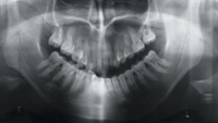 |
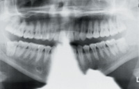
| Figure 1. The head has been dropped too much as evidenced by the excessive smile line, elongated maxillary anterior teeth, and foreshortened mandibular anterior teeth. There is overlapping of the maxillary premolar teeth. The images of the anterior teeth are also narrow and fuzzy. |
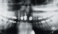 |
| Figure 2. The images of the maxillary central incisor teeth in particular (also the mandibular central incisor teeth) appear very broad because the patient is positioned too far back. The lateral incisor and cuspid on the patient’s right side are broader than on the left side because the patient is not positioned symmetrically. Apical to the maxillary right posterior teeth are two elongated, horizontal opacities, double images of an earring on the patient’s left side. Apical to the left mandibular lateral incisor is a small triangular opacity caused by the lead apron positioned at the back of the neck. A slumped vertebra created the poorly demarcated vertical opacity superimposed over the mandibular incisor teeth. |
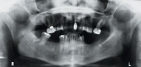 |
| Figure 3. There is a broad, horizontal opacity over the images of the apices of the maxillary incisor and premolar teeth caused by the pharyngeal air space. The smile line has been lost and there is a broad horizontal opacity apical to the maxillary teeth because the chin was raised too much. The anterior teeth are fuzzy because the patient is seated too far forward. |
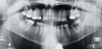 |
| Figure 4. The lucency of the pharyngeal air space is preventing visualization of the images of the apices of the maxillary teeth. The lucency over the ascending ramus of the mandible should not be mistaken for a fracture. The anterior teeth are slightly fuzzy. The midline vertical opacity of the vertebra is observed and the opacity of the lead apron is seen to the left of the midline at the bottom of the radiograph. |
 |
| Figure 5. The lead apron at the back of the patient is obliterating the mandibular anterior teeth. A vague pharyngeal space is visible. |
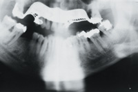 |
| Figure 6. Patient denied having any removable appliances, which can clearly be seen in the maxilla. Midline opacity of the spine is evident, partially obliterating the images of the mandibular anterior teeth. The anterior teeth are fuzzy. On the left side of the radiograph, the hyoid bone is superimposed on the posterior region of the mandible |
 |
| Figure 7. The part of the necklace that is at the back of the neck can be seen superimposed over the apices of the mandibular anterior teeth. A mandibular removable chromium cobalt denture is visible. The dorsum of the tongue, inferior to the pharyngeal space, is prominent. |
Sometimes a patient is embarrassed to inform the technician that they are wearing removable bridges, and these images will then appear on the radiograph (Figures 6 and 7). Also, patients sometimes are reluctant or are unable to remove tongue rings, nose rings or earrings. Removal of all such jewelry is desirable, as metallic objects will often throw a large ghost image on the opposite side of the face (Figure 2), or prevent visualization of the images of teeth. Double images are always larger, more poorly demarcated, and positioned in a more superior location on the opposite side of the radiograph.
Where patients are wearing complete dentures with no metal clasps or bars, it is advisable to leave the dentures in the mouth as the patient can then be better positioned in the focal trough, resulting in clearer images. When the teeth are acrylic nothing will be seen on the radiograph; where the denture has porcelain teeth, these images will appear between the
alveolar ridges but will not interfere with viewing relevant anatomy or pathology.
VIEWING THE TMJ
When purchasing a panoramic machine it is preferable to buy one that utilizes a film size that has a 6-inch width rather than a 5-inch width. With the smaller film width, the TMJ more often does not appear on the radiograph (Figures 1, 4, and 6); this can be seen particularly for patients with a large face. Also, the more the face/chin is dropped, the greater the vertical distance of the face and the less likely the TMJ will be imaged on a radiograph that is 5 inches wide. In the radiograph in Figure 1, the film is 5 inches wide and the outline of the superior head of the head of the condyles is not completely observed. These structures would be seen with a 6-inch film. Also, if the patient is seated too far back in the focal trough, the TMJ area will move posteriorly and the images will not appear on the radiograph. Images of carotid calcifications or calcified lymph glands (which may be present in tuberculosis) are also more likely to be seen on a 6-inch wide film
CONCLUSION
Some of the more common technical errors seen in panoramic radiographs have been discussed and illustrated, and approaches to correction and avoidance have been reviewed.
Awareness and avoidance of the errors discussed will improve the quality of panoramic radiographs in clinical practice, thus providing a higher diagnostic yield.
Dr. Serman is professor of oral radiology, Division of Oral and Maxillofacial Surgery, at the School of Dental and Oral Surgery, Columbia University in New York, NY. Dr. Serman is also the American director on the board of directors of the International Association of Dento Maxillo Facial Radiology. At the Scientific Congress of the International Association of Dento Maxillo Facial Radiology (IADMFR), held in Glasgow, Scotland, in 2001, Dr. Serman was elected as a fellow of the IADMFR, the tenth time in the history of the association that this award has been made.
Dr. Horrell is an assistant professor of oral radiology, Division of Oral and Maxillofacial Surgery, at the School of Dental and Oral Surgery, Columbia University in New York, NY.
Dr. Singer is an associate professor in the Division of Oral and Maxillofacial Radiology, University of Medicine and Dentistry of New Jersey, in Newark, NJ.


