When observing access preparations during our hands-on courses we find that many of the preparations are inadequate. Is it because dentists are not exactly sure what constitutes a good access? Is it because they don’t really appreciate its benefits, or is it because not enough time is allotted in dental school due to an overburdened curriculum? The most likely answer is all of the above.
Much has been written about access and the fact that a good access is a must for visualization and optimum cleaning and shaping. Recognizing that there are many approaches to making access we welcome the chance to present our technique. You will appreciate the benefits of a perfect access every time you enter a canal. The purpose of this article is to help you improve your access preparation and show how to make a perfect access in just a few minutes.
What is an ideal access?
An ideal access provides a straight-line path to the canal orifice and to mid-root. It eliminates the need for a mirror and searching for the orifice every time you try to enter the canal with an instrument. We make our point with the following demonstration. A cup is placed on the floor in the corner of a room. The cup represents the canal orifice, the corner of the room represents the path leading to the cup (canal orifice), and a long stick represents the root canal instrument. Looking away from the cup it is easy to direct the stick into the cup orifice. The corner is located (by feel), and it is followed down into the cup. If the cup is moved away from the corner even a short distance, the path does not lead to the cup. A tedious “hunt and peck” technique must be used to enter the orifice—a sure way of taking all the fun out of doing root canals.
When making access we concentrate just on access, and think about nothing else until it is correct. Once you are in this mind-set you will find that the time you spend on access will save you time on everything else. A perfect access will also reduce the stress of a difficult root canal treatment. A poor access increases the difficulty of even easy cases.
ACCESS—NOT TOO LARGE, NOT TOO SMALL
Some dentists make large accesses for better visibility, whereas others make them small for easier restorability and less likelihood of fracture. A perfect access is neither too large nor too small. It is exactly what it is supposed to be to perform its function correctly. Expecting perfection is asking a lot, but before dismissing it as an impossible goal, give us a chance to explain.
 |
 |
| Figure 1a. Correct access. Each canal orifice is located in corners formed by two access walls. The corners provide paths that guide instruments, etc, directly to canal orifices and into canals. | Figure 1b. Incorrect access—too large. Canal orifices are not located in corners formed by two access walls and therefore the corners do not provide paths to the orifices. Instead, the paths lead to ledges that make entering the orifice much more difficult. |
 |
| Figure 1c. Incorrect access—too small. All orifices are not visible. Canal orifices are not located in corners formed by two access walls and no paths exist for guidance. |
A perfect access is easily attainable because the goal of an access is clearly defined (stated previously), and we have certain anatomical checkpoints that guide us in making access. The checkpoints of guidance are the canal orifices. The locations of the canal orifices dictate the shape of the access (Figure 1a). After finding the orifices we make paths (or grooves) that lead to them (recall the cup demonstration). The paths are made in chamber walls much like making retention grooves for restorations. You already have the necessary skills. Once you know what to do, it’s easy.
WHY ARE LARGE ACCESS OPENINGS NOT DESIRABLE?
The problem with too large an access is that it often removes the dentin needed for making paths to canal orifices. With a proper access—one with guide paths—root canals can be done mostly by feel. If you need to see the orifice to enter it, be assured there is something very wrong with the access. Figure 1b shows an access opening that is too large.
WHY ARE SMALL ACCESS OPENINGS NOT DESIRABLE?
Too small an access has its own problems. If we can’t see an orifice and miss treating the canal, the case is subject to failure. To minimize the chance of missing canals, always remove the entire chamber roof. No compromising.
Another disadvantage of a small access is its inability to provide paths to canal orifices. Paths associated with a small access would tend to guide root canal instruments to locations other than where the orifices are positioned.
Another major risk of a small access is instrument separation, especially with rotary instruments. A small access forces instruments to bend excessively just to enter a canal. Such bending hastens the failure of rotary instruments from metal (cyclic) fatigue. Failure can occur quite rapidly. Figure 1c shows an access opening that is too small.
The point we wish to make is that a perfect access is neither large nor small—it is just right because our guide paths have made it so. We feel so strongly about having guiding paths that when insufficient tooth structure is present we place a cotton pellet in the chamber, build up the crown with a rapid setting material, and then cut the perfect access.
STRIVE FOR STRAIGHT-LINE ACCESS TO MID-ROOT
The mention of excessive instrument bending before entering a canal leads us to another location of instrument bending—the coronal curve. We want to avoid instrument bending after entering a canal just as we want to avoid the bending before entering a canal. As will be described later, we straighten coronal canal curvatures with a technique called anti-curvature filing.
HOW DO WE KNOW WHEN WE HAVE ACHIEVED A PERFECT ACCESS?
 |
 |
| Figure 2a. Radiograph showing a No. 15 K file in the MB canal prior to straight-line access. Note that entry is from the distal. | Figure 2b. Radiograph after completing access. The file reveals straight-line access to mid-root. The coronal curvature (Figure 2a) has been eliminated. |
 |
| Figure 2c. Radiograph showing root canal filled. Note how the removal of coronal dentin with anti-curvature filing provides a more direct access to mid-root. |
A perfect access is easy to determine with a No. 15 K file. If the file enters each canal easily and maintains a straight-line posture with the long axis of the root (when not being held in hand), you know the access is correct. It also should be easy to enter canals without mirrors or looking. If easy entry and a straight-line posture of the No. 15 K file are lacking, correct the access before going any further. Figures 2a, 2b, and 2c show a maxillary molar before and after access.
LET’S GET ORGANIZED
Getting organized means having the required instruments when and where they are needed, all in one convenient place. This is the key to saving time when making access. Leaving the operatory to find an instrument is a waste of time. To help get organized we developed a kit to hold the instruments we use most often for access. It’s called the StraightLine Access Kit.
LIGHTSPEED STRAIGHTLINE ACCESS TECHNIQUE
Now that we have discussed access principles, let’s begin the “how to.” We highly encourage magnification during access and have found that 3.5X loupes usually are sufficient. The access steps are listed as follows.
 |
| Figure 3. Pretreatment radiograph showing a size 15 K file in the MB canal. The tip is slightly apical to the coronal curve. Straight-line access requires removing coronal curvatures to about mid-root as shown in Figure 10. Excessive curvatures are hazards for all rotary instruments. They contribute to instrument separation from metal fatigue, ledges and other mishaps. |
The pretreatment radiograph reveals an abrupt coronal curvature in the MB root of a maxillary molar (Figure 3). Part of a perfect StraightLine access requires removing this curve to about mid-root (Figure 10).
Step 1. Make an Access to the Pulp Chamber (Figure 4)
 |
| Figure 4. Prior to beginning access, study the occlusal surface. Mentally position the canal orifices (dashed circles) on the occlusal surface and mentally design an initial access outline form as shown. Penetrate to the pulp chamber keeping the same outline form. Be conservative—it’s easy to remove more tooth structure but not to replace it. |
Look at the occlusal surface of the crown and study its shape. Mentally position the approximate locations of the canal orifices on this shape and come up with a mental design of the initial access opening. Cut this mental image of the access on the occlusal surface with a No. 331 high-speed bur (or bur of your choice). Continue penetrating deeper and deeper with the same shape until you penetrate the pulp chamber. We prefer this technique rather than making a small hole to the chamber. A larger penetration shape allows more light and better visibility within the chamber. Be conservative. Additional tooth structure can always be removed later.
After gaining access to the chamber, thoroughly clean all of its walls and floor with an endodontic spoon using vigorous scraping, copious irrigation, and suction. Don’t minimize the importance of this step. You have to see what is on the chamber floor. Otherwise, you risk missing a canal or perhaps taking more time than necessary to find an orifice.
Remove any remaining pulp chamber roof with a laterally directed long tapered bur, being sure not to touch the floor of the chamber. We believe that a round bur used to “lift away” the roof from underneath will often make indentations in the chamber walls below the level of the roof. We don’t want this because we want chamber walls as smooth as possible—like the walls of a crown preparation. We are now finished with the initial access opening—we’ll refine it after we have located all the canals.
Step 2. Locate All of the Canal Orifices (Figure 5)
 |
| Figure 5. Locate all canal orifices. They dictate the final shape of the access preparation. |
Locate the canal orifices either by sight (large size orifices), with an endodontic explorer (medium sizes), or with a file (small sizes). Then instrument all canals to about mid-root with a No. 10 K file until it fits loosely. Don’t try to reach working length at this stage. Remove pulp tissue from canals with barbed broaches whenever possible.
Step 3. Move the Mesial Canal Orifice(s)
 |
| Figure 6a. Anti-curvature filing of the MB canal (maxillary molar). Direct the blade of the Hedstrom files (Nos. 15, 20, and 25, in that sequence) against the canal orifice and coronal canal walls (arrows) in the direction away from the furcation (mesio-buccally). Anti-curvature (against the curve) filing removes the coronal curve and “uprights” the coronal part of the canal. |
 |
| Figure 6b. Anti-curvature filing of a mandibular molar. The MB and ML canal orifices and coronal canal curvatures are “uprighted” with anti-curvature filing (arrows) in the direction away from the furcation (mesially). The before line (red) indicates the approximate direction of entry (from the distal) and coronal curvature of the first exploring K file. The after line (blue) indicates the desired direction of entry (straight down) and removal of the coronal curvature after anti-curvature filing. |
In maxillary molars the MB orifice and the coronal third of the canal are moved away from the furcation with anti-curvature filing (Figure 6a). In mandibular molars anti-curvature filing moves the MB and ML orifices and coronal third of the canals away from the furcation (Figure 6b). “Anti-curvature filing” is so named because the filing is directed against the coronal curvatures to straighten them out. This is done with Hedstrom files, forcefully directing their blades away from the furcation and removing dentin at the orifice and coronal canal walls with a pulling motion. If you are not familiar with the concept of anti-curvature filing, viewing Figures 6a and 6b should help. Anti-curvature filing is done with Hedstrom files sizes 15, 20, and 25 (in that sequence). We use Hedstroms because they remove dentin rapidly and give us excellent control. They should cut dentin without contacting enamel. If they do, remove the enamel that gets in the way with a tapered diamond.
Anti-curvature filing (Step 3), along with coronal canal flaring (Step 4), and straight-line access paths (Step 5), enable instruments to reach the mid-root of mesial canals in a straight line, parallel to the long axis of the tooth rather than from the distal. Anti-curvature filing also reduces the chance of coronal strip perforations by rotary instruments during coronal flaring (Step 4) and reduces the possibility of instrument separation.
Step 4. Flare the Coronal Part of the Canal
The coronal third of the canal can be flared with many different instruments such as Profile, Quantec, GT, Pro
Taper, K3, AET, and others. Because the majority of dentists may still be using Gates-Glidden drills (GG) we will use them for this step. GGs can be used sequentially in sizes 2, 3, and 4 or in the reverse order. We prefer the 2, 3, and 4 order because size 2 makes a path for the size 3 that makes a path for the size 4. In our opinion, when GGs are used in sizes 4, 3, and 2 it seems to take more time and effort.
 |
 |
| Figures 7a and 7b. Use Gates-Glidden drills Nos. 2, 3, and 4 (or instruments of your choice) to flare the coronal third of the canal. To avoid perforations or ledges coronal flaring should be done only after anti-curvature filing has been completed. |
Use a light pecking motion to advance a GG so that you can feel when it encounters a coronal curve (Figure 7a). Using too much force may drive it into the canal wall and make a ledge. In molars we recommend taking GGs no more than about 4 mm into the canal—approximately the blade length of the No. 4 GG (Figure 7b).
When the distal and palatal canals of molars are oval or “C” shaped, wipe the walls clean with GGs using a light lateral force. Beware, a heavy force may bend or break the drills.
Step 5. Complete the StraightLine Access
 |
| Figure 8a. Use a long tapered diamond with a tip size slightly smaller than the size made by the flaring instrument (at the canal orifice). |
 |
| Figure 8b. First make guiding paths to all canal orifices with the diamond. Then, move the diamond from orifice path to orifice path to make smooth access walls and complete the access. |
Make a “path” from the top of the crown to each canal orifice as follows: (a) without activating the high-speed handpiece place the tip of a long tapered diamond firmly (by feel) into the canal orifice previously shaped by the GG drills (Figure 8a); (b) raise the tip of the diamond just slightly above the orifice; and then (c) activate the handpiece and make a path (from the orifice to the top of the crown) by tilting the diamond to line up with the long axis of the canal. Important: the tip of the diamond remains always in the same position—slightly above the canal orifice.
After a path to each orifice has been made, refine the remainder of the access by moving the diamond from orifice path to orifice path around the periphery of the access. This removes any projections of the chamber roof and makes smooth continuous access walls from the chamber floor to the top of the crown. This completes a standard StraightLine access (Figure 8b).
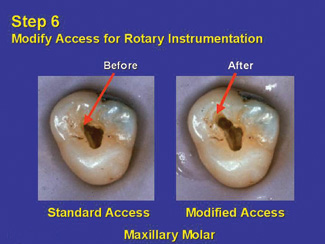
Step 6. Modify the Access for Rotary Instrumentation
 |
| Figure 9a. The MB canal of the maxillary molar is usually the most difficult to enter. To make entry easier the standard MB guiding path (before, left arrow) is tilted towards the MB line angle (after, right arrow). |
 |
| Figure 9b. The ML canal of the mandibular molar is usually the most difficult to enter. To make entry easier the standard ML guiding path (before, left arrow) is tilted towards the ML line angle (after, right arrow). |
 |
| Figure 9c. Photographs showing the amount of handpiece tilting required for maxillary molars. The handpiece is tilted so that it can be withdrawn without contacting the teeth of the opposing arch. |
 |
| Figure 9d. Photographs showing the amount of handpiece tilting required for mandibular molars. The handpiece is tilted so that it can be withdrawn without contacting the teeth of the opposing arch. |
The most difficult canals to enter with rotary instruments are the MB of maxillary molars (Figure 9a) and the ML of mandibular molars (Figure 9b). A perfect access for rotaries requires modification of the standard “path” to make entering these difficult canals easier with rotary instruments. This path modification also reduces the possibility of instrument separation from excessive bending.
Remember that radiographs are two-dimensional and that there are curves in the third dimension as well. Three-dimensional curves are challenging for all rotary instruments, especially those that lack flexibility.
For maxillary molars, position the high-speed diamond at the orifice of the MB canal as was done in Step 5a. Then repeating Steps 5b and 5c, modify the standard path by tilting the diamond towards the MB line angle (Figure 9a) until the handpiece can be withdrawn without contacting the lower teeth (Figure 9c).
Mandibular molars require modifying the ML path (Figure 9b) for easier entry of rotary instruments. Following the same procedure used for maxillary molars modify the standard path for the ML canal by tilting the diamond towards the ML line angle until the handpiece can be withdrawn without hitting the upper teeth (Figure 9d).
WRAP UP
 |
| Figure 10. StraightLine access complete. Note that the original coronal canal curvature (left) has been straightened (“uprighted”) and a straight path to mid-root has been attained (right). |
Clinically, we allocate roughly 9 minutes to make a perfect access in routine molars. Of course, it could take much longer if the canals cannot be easily found and entered. There is no good reason for not making an ideal access in every case (Figure 10). If it’s not correct initially, take a few more minutes to get it right.
|
Table. Do’s and Don’ts for Successful Access Do’s Don’ts |
We hope you will dedicate yourselves to achieving a perfect access. Give it the time and importance it deserves and you will be well rewarded—immediately (see Table).
Acknowledgment
The authors wish to thank Mr. Steven Senia, BSIE, MBA, for his contributions to this article.
Dr. Senia is a diplomate of the American Board of Endodontics, a former Journal of Endodontics Editorial Board member, and a consultant for NASA’s space program. He has lectured throughout the world and published extensively. He can be contacted at DrSteveSenia@aol.com.
Disclosure: Dr. Senia is the co-inventor of the LightSpeed root canal instrument and SimpliFill obturation systems and a member of the LightSpeed Endodontics Board of Directors.
Dr. Wildey served 4 years as a general dentist in the US Air Force and is presently in an endodontic practice in the Dallas/Fort Worth area in Texas. He is the primary author of two articles published in a major national dental journal.
Disclosure: Dr. Wildey is the co-inventor of the LightSpeed root canal instrument and SimpliFill obturation systems and a member of the LightSpeed Endodontics Board of Directors.
Note: The authors have created a StraightLine Access Kit, step-by-step instructions on video, and a printed technique guide to help you make a perfect access. For additional instruction and hands-on experience, they offer hands-on courses as well. If you’d like to learn more about their StraightLine Access Kit and courses, please call (800) 817-3636 or visit www.LightSpeedUSA.com.


