Three-dimensional imaging in dentistry offers many advantages with respect to diagnosis and treatment planning. This article focuses on cone beam computerized tomography (CBCT), which combines conventional x-ray and computerized volumetric reconstruction to reproduce a 3-dimensional image. A search of the peer-reviewed dental literature was performed to determine clinical applications in dentistry. Applications include 3-dimensional imaging for implant placement, extraction or exposure of impacted teeth, definition of anatomical structures, airway analysis, and temporomandibular joint imaging related to the diagnosis of joint disorders.
BACKGROUND
 |
 |
|
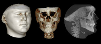
Figure 1. Images taken with CBCT technology are easy to understand and accurately represent the patient’s craniofacial structures. (Note: The CB MercuRay [Hitachi Medical Corporation] was used to produce the images in Figures 1 to 3 and 6 to 11.) |
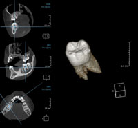
Figure 2. The CBCT image can be seen as slices or cuts, separated by sagittal, coronal, and axial views, with reference lines that make it easy to understand the location of the area being examined. |
 |
|
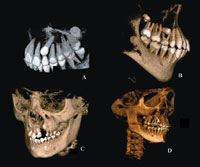
Figure 3. The field of view represents the area that can be captured when imaging a patient. Possible fields of view include (A) 3 inches, (B) 6 inches, (C) 9 inches, and (D) 12 inches. (Image courtesy of Hitachi Medical Systems America.) |
CBCT is a method to acquire 3-dimensional radiographic images that is becoming increasingly popular in dentistry. The resulting images are user-friendly and provide far more information than conventional 2-dimensional radiographs. Three-dimensional imaging is capable of capturing both skeletal and soft tissues, which can then be displayed together or separately (Figure 1). Like earlier CT technology such as spiral and fan CT, “slice-by- slice” axial, sagittal, and coronal images can be observed, but CBCT software also incorporates reference lines that make location of these slices less complicated. For example, even when observing only the coronal view or a small segment of a complete image, lines in the sagittal slice view will indicate the height and position of the slice or object being analyzed (Figure 2).
CBCT is digital by nature and uses a computer program to construct a 3-dimensional volume from a series of 250 to 300 2-dimensional images. CBCT terminology reflects that emphasis. For instance, voxel is used instead of pixel, since it is referring to volume and not to a 2-dimensional space. The image files are the DICOM (Digital Imaging and Communications in Medicine) standard, namely, the universal format for 3-dimensional images in the medical field.1 Therefore, a 3-dimensional CBCT image will have a file extension of “dcm,” instead of a digital picture that would have an extension such as “tif,” “jpeg,” etc.
The region of interest, usually abbreviated as ROI, is the 3-dimensional volume that the clinician wants to evaluate. For example, when asking for a periapical radiograph of the mandibular incisors, the ROI is that incisor area. The smaller the ROI, the better the resolution obtained for that image. The resolution often is related to the size of the field of view (FOV), which is the resulting size of the image (Figure 3). For example, if the clinician wants to visualize a cyst in the mandibular incisor area, and a large FOV that includes the entire head is used, the observer must zoom to the ROI, and the image quality will not be as good as a FOV that was focused only in that incisor area.
This concept is similar to what occurs for digital photography. If the clinician wants to see a central incisor in detail, a good starting point would be an intraoral picture of the target area, not the full smile. In the latter scenario, zooming in would make the incisor appear fuzzy, indicating poor resolution. The resolution in CBCT images ranges from 0.1 to 0.5 mm.
CONE BEAM COMPUTERIZED TOMOGRAPHY
 |
|
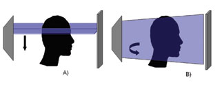
Figure 4. Illustration showing the difference between the data capture system of regular CT and CBCT. (A) A regular CT machine captures the data in a fan fashion; (B) the CBCT captures the data in a volumetric fashion. |
Craniofacial CBCT was designed to counter some of the limitations of earlier generations of CT scanning devices and to make 3-dimensional technology practical for dentistry. The radiation source consists of a conventional, low-radiation x-ray tube, and the resultant beam is projected onto a panel detector, producing a more focused beam and considerably less scatter radiation compared to the helical CT devices (Figure 4).2,3,4 The total radiation is approximately 20% of that of a helical CT and can be equivalent to exposure during a full-mouth periapical series.5
The innovations mentioned above are significant, since they allow the CBCT unit to be less expensive and smaller in size than a traditional CT machine. When compared to earlier generation CT scanners, CBCT is more sensitive and more accurate, requires less radiation, captures the maxilla and mandible in a single rotation of the x-ray source, and is more cost-effective for patients.6,7,8 Another advantage of the CBCT technology over earlier generations of CT such as helical CT is the low level of metal artifacts in primary and secondary reconstructions.9 An image taken with helical CT of an area close to a metallic restoration, a crown, or an implant is very difficult to analyze and diagnose because of the artifacts and distortions that the presence of the metal would create. This is a major limitation in the use of helical CT images, since many patients have metal present in their mouths. With CBCT technology, the area around the metal presence is usually of diagnostic quality. CBCT offers surface as well as radiographic view modes. The latter are similar to traditional radiographs familiar to dental practitioners.
 |
|
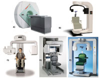
Figure 5. Currently available cone beam scanners approved for use in dentistry: (A) NewTom 3G (courtesy of Aperio Services); (B) ILUMA (courtesy of IMTEC); (C) CB MercuRay (courtesy of Hitachi Medical Systems America); (D) i-CAT (courtesy of Imaging Sciences); and (E) 3D Accuitomo (courtesy of J. Morita USA). |
Five CBCT systems are currently on the market, and 2 other systems will soon be available. The available CBCT systems (Figure 5) are NewTom 3G (Quantitative Radiology), i-CAT (Imaging Sciences International), CB MercuRay (Hitachi Medical Corporation), 3D Accuitomo (J. Morita Manufacturing), and the ILUMA (IMTEC Imaging). The available CBCT machines differ in size, settings, area of image capture (field of view), and clinical usage (Table).
The NewTom 9000 was the first CBCT device for the dental market. When using a NewTom, the patient is imaged in a supine position, and scans of the head and neck are completed in 36 seconds. The system offers 3 possible fields of views (6, 9, and 12 inches). According to the manufacturer, the system is able to produce a voxel resolution up to 0.16 mm.
The i-CAT cone beam system captures the image with the patient sitting upright, and the scan time varies from 20 to 40 seconds. According to the manufacturer, the i-CAT provides no distortion, a 12-bit grayscale, and a voxel size resolution of 0.2 mm. One early criticism of the system was the distortion of the facial tissues a chin rest produced when the patient was positioned in the device. Imaging Sciences has improved the patient positioning device, and this problem has been eliminated in the later versions.
|
Table. Specifications of the Currently Available Cone Beam CT Machines Approved for Use in Dentistry. |
||||||||||||||||||||||||||||||||||||||||||||||||||||||||||||
*Scan time is how long the machine takes to take an image and does not represent exposure time. For example, in the NewTom 3G even though the scan time is 36 seconds, the actual exposure time is only 5.4 seconds. |
The CB MercuRay is a considerably larger unit and allows for different fields of view. A scan time of 10 seconds through a rotation of 360° provides 288 views that can be seen either as 2-dimensional or 3-dimensional images. The CB MercuRay offers 3 different fields of view and is the fastest CBCT machine currently available. This is an advantage, since patient movement is reduced during image capture.
The 3D Accuitomo was developed as a collaboration between the School of Dentistry at Nihon University and J. Morita Manufacturing. This apparatus focuses on specific structures, offering a field of view of approximately 1.2×1.6 inches. This compact unit has the advantage of requiring only 1.6 times the space of a conventional dental panoramic machine.
The ILUMA is the latest full-view head-and-neck imaging CBCT and uses a fixed field of view. The ILUMA is available as 2 different versions, the OrthoCAT and the DentalCAT, with respective fields of view of 7.5×7.5 inches and 4×6.7 inches.
CLINICAL APPLICATIONS OF CBCT IN DENTISTRY
With CBCT technology, all radiographic images can be taken in less than a minute. Dental clinicians can have the diagnostic quality of periapical radiographs, panoramic radiographs, cephalograms, occlusal radiographs, and TMJ images at their disposal, along with views that cannot be produced with regular radiographic machines such as axial and cross-sectional views. A number of clinical applications have already been reported in the literature.10 A search of the peer-reviewed dental literature from 1966 to 2006 was performed using Medline and PubMed, a review of pertinent dental textbooks, the Internet, and personal communication with authors and organizations. The key words used were Cone Beam, CBCT, and CBVT. The results were analyzed in order to find reports and comments on clinical applications of CBCT technology in dentistry. The results were as follows:
Impacted Teeth
 |
|
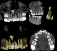
Figure 6. CBCT images of a patient with an impacted supernumerary tooth. (A) anterior view of the maxilla in the radiographic mode; (B) view of the right half of the maxilla in the radiographic mode; (C) surface view of the anterior right segment of the maxilla; (D) anterior view of the maxilla in the surface mode; and (E) occlusal view of the maxilla in the radiographic mode. |
Impacted maxillary cuspids have been reported to be distributed as 85% palatal and 15% buccal.11 The tube shift method has traditionally been used to locate the position of these cuspids and provides an approximation of the level of difficulty associated with the management of these teeth. This method is labor intensive.
The use of CBCT has proven useful in the management of patients with impacted teeth (Figure 6).11,12 The CBCT allows for a more precise analysis of the extent of the pathology related to the ectopic tooth. Clinical reports using 3-dimensional imaging have shown that the incidence of root resorption of teeth adjacent to impacted teeth is greater than previously thought.11 CBCT images can be used to locate the precise position of ectopic cuspids and to design treatment strategies that would result in less invasive surgical intervention. Computer-and image-guided surgical exposure allows for less invasive surgery, smaller incisions, more conservative flap design, and overall reduced morbidity associated with the surgery. 11,12
PATHOLOGY
 |
|
Figure 7. CBCT images of a patient with a mandibular cyst. (A) mesial view of right half of the mandible in surface mode; (B) anterior view of the mandible in the surface mode with measurements in mm; (C) lingual view of the mandible in surface mode with measurements in mm; (D) radiographic cross-sectional view of the maxilla and mandible, and (E) panoramic view. |
Another use of CBCT is the location of (oral) pathologic lesions such as periapical cysts (Figure 7). CBCT has been evaluated for the detection of carious lesions and has shown better results than F-speed film in assessing the depth of proximal lesions.13 Centers including Case Western Reserve University and Loma Linda University, among others in the United States, have begun to adopt CBCT imaging into routine dental examination procedures. Preliminary, unreported findings suggest that the incidence of oral abnormalities, ie, cysts, ectopic teeth, and supernumerary teeth, is higher than previously suspected.
Airway Analysis
 |
|
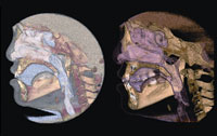
Figure 8. Analysis of the airway with only a lateral film would not be able to identify a possible airway lateral constriction abnormality. With CBCT the airway can be segmented and analyzed volumetrically in 3 dimensions. |
CBCT technology provides a major improvement for evaluation of the airway, allowing for 3-dimensional and volumetric determinations (Figure 8). Airway analysis conventionally has been carried out by using lateral cephalograms. A recent study comparing lateral cephalograms to CBCT imaging found that there was moderate variation in the measurements of upper airway area and volume.14 Three-dimensional airway analysis will be useful for the understanding of more complex conditions such as obstructive sleep apnea (OSA) and enlarged adenoids. CBCT has demonstrated significant differences in airway volume and the anteroposterior dimension of the oropharyngeal airway between OSA patients and gender-matched controls.15
Implant Planning and Bone Quality Assessment
 |
|
Figure 9. Alveolar height and width assessment used for planning dental implants. The CBCT image gives a true 1:1, 3-dimensional representation of the patient. |
Implantologists have long appreciated the value of 3-dimensional imaging. Conventional CT scans are used to assess the osseous dimensions, bone density, and alveolar height, especially when multiple implants are planned (Figure 9). Locating landmarks and anatomy such as the inferior alveolar canal, maxillary sinus, and mental foramen occurs more accurately with a CT scan. The use of the third dimension has improved the clinical success of implants and their associated prostheses, and led to more accurate and aesthetic outcomes.16-22
With CBCT technology both the cost and effective radiation dose can be reduced. CBCT has been in use in implant therapy and may be employed in orthodontics for the clinical assessment of bone graft quality following alveolar surgery in patients with cleft lip and palate.23,24 The images produced provide more precise evaluation of the alveolus. This technology can help the clinician determine if the patient should be restored or if teeth should be moved orthodontically into the repaired alveolus.
Location of Anatomic Structures
 |
|
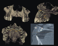
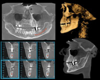
Figure 10. Images produced from a single exposure for the purpose of dental implant planning. The images here are panoramic and cross-sectional views with the mandibular canal marked, as well as a surface and radiographic (maximum intensity projection) view with the stent in place. |
Anatomic structures such as the inferior alveolar nerve, maxillary sinus, mental foramen, and adjacent roots are easily visible using CBCT (Figure 10).18 The CBCT image also allows for precise measurement of distance, area, and volume. Using these features, clinicians can feel confident in the treatment planning for sinus lifts, ridge augmentations, extractions, and implant placements.
Temporomandibular Joint (TMJ) Morphology
 |
|
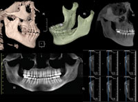
Figure 11. Different possible views of the TMJ complex by using CBCT, showing in this case a fracture. (A) and (B) surface mode showing the extent of the fracture; (C) radiographic mode; (D) panoramic view; and (E) cross-sectional view in the radiographic mode. |
CBCT imaging of the temporomandibular joint has been evaluated and compared to other methods.7,25,26,27 Results indicate better imaging with CBCT compared to traditional radiography and helical CT.7 The CBCT showed greater sensitivity and accuracy than the helical CT in the identification of mandibular condyle abnormalities. Condylar resorption is reported to occur in 5% to 10% of patients who undergo orthognathic surgery.28 Recent 3-dimensional studies have attempted to understand how the condyle remodels, and preliminary data suggest that much of the condylar remodeling is a direct result of the surgical procedure.28 TMJ changes following distraction osteogenesis and dento-facial orthopedics require further study.
CBCT images provide high diagnostic quality (Figure 11) with lower patient radiation exposure as compared to conventional CT techniques. Therefore, CBCT should be considered as the imaging technique of choice when investigating bony changes of the TMJ.25
Orthodontics
CBCT technology is able to capture all radiographic records necessary for orthodontic diagnosis in less than 1 minute.29 Three-dimensional visualization of the patient allows for a more accurate evaluation of both dental and skeletal asymmetries and can provide a more thorough outcome assessment.
RADIATION EXPOSURE
Even though cone beam technology is able to provide 3-dimensional volumetric images with up to 4 times less radiation than a conventional CT,30,31 the effective radiation depends on the settings used (kVp and mA). The use of lower mA and/or collimation are some of the ways to reduce the amount of radiation, but at the same time the image quality may suffer. Exposure dose from a CBCT machine has been reported to be as low as 45 µSv (micro-sievert, SI unit for ionizing radiation) to as high as 650 µSv.32,33 Exposure from a full-mouth series of analog radiographs has been reported to be 150 µSv,34 and 54 µSv for an analog panoramic radiograph.35,36 As a comparison, a roundtrip airplane flight from Paris to Tokyo exposes passengers to an effective dose of 139 µSv.37,38
In 2001, a report associating the use of conventional CT in children to radiation-induced cancer39 resulted in CTs being adjusted downward to have an effective dose ranging from 2,600 µSv to 6,000 µSv.40 Even at the highest settings possible, none of the CBCT units will provide anything near that dose.
The ADA Council on Scientific Affairs recommends the use of techniques that would reduce the amount of radiation received during dental radiography. Known as the As Low As Reasonably Achievable (ALARA) principle, this includes taking radiographs based on the patient’s needs (as determined by a clinical examination), using the fastest film compatible with the diagnostic task, collimating the beam to a size as close to that of the film as feasible, and using leaded aprons and thyroid shields.41 An accepted ratio between exposure and image quality needs to be reached in order to apply the ALARA principle. Depending on the objective and desired outcome, alternative technologies should be explored, since it may offer a less invasive way of creating a 3-dimensional image.42,43
DISCUSSION
CBCT is capable of imaging hard-tissue and most soft-tissue structures. However, this technology does not have the ability to precisely map muscles and their attachments. These structures would have to be imaged using conventional magnetic resonance imaging technology, which does not expose the patient to ionizing radiation. Further, CBCT soft-tissue images do not show the color of the skin. In order to obtain photographic quality results, manipulation of the images is required. Successful attempts to add tissue color maps to conventional CTs have been reported and may eventually be applied to CBCT technology.43 This may be an alternative to extraoral photography. Meanwhile, devices such as stereo-photogrammetry and laser scanning are still the state of the art for capturing soft-tissue color images.
As with all new technology, cost is a major concern. Cost of a CBCT machine can range from $150,000 to $300,000. All 5 companies sell the CBCT devices as standard base packages; peripherals can increase the cost. Also, a substantial post-purchase maintenance cost is required for most systems. The purchase of a CBCT system is very different than the purchase and use of traditional radiographic systems and generally requires a dedicated staff member with considerable training.
CONCLUSION
The incorporation of the third dimension into practical dental and craniofacial imaging is now a reality. The future of craniofacial and dental imaging is exciting as the paradigm shifts from landmarks, lines, distances, and angles to surfaces, areas, and volumes.
References
1. Farman AG. Raising standards: digital interoperability and DICOM. Oral Surg Oral Med Oral Pathol Oral Radiol Endod. 2005;99:525-526.
2. Danforth RA, Peck J, Hall P. Cone beam volume tomography: an imaging option for diagnosis of complex mandibular third molar anatomical relationships. J Calif Dent Assoc. 2003;31:847-852.
3. Mah J, Hatcher D. Current status and future needs in craniofacial imaging. Orthod Craniofac Res. 2003;6(suppl 1):10-16; 179-182.
4. Sukovic P. Cone beam computed tomography in craniofacial imaging. Orthod Craniofac Res. 2003;6(suppl 1):31-36; 179-182.
5. Mah JK, Danforth RA, Bumann A, et al. Radiation absorbed in maxillofacial imaging with a new dental computed tomography device. Oral Surg Oral Med Oral Pathol Oral Radiol Endod. 2003;96:508-513.
6. Winter AA, Pollack AS, Frommer HH, et al. Cone beam volumetric tomography vs. medical CT scanners. N Y State Dent J. 2005;71:28-33.
7. Honda K, Larheim TA, Maruhashi K, et al. Osseous abnormalities of the mandibular condyle: diagnostic reliability of cone beam computed tomography compared with helical computed tomography based on an autopsy material. Dentomaxillofac Radiol. 2006;35:152-157.
8. Hashimoto K, Kawashima S, Araki M, et al. Comparison of image performance between cone-beam computed tomography for dental use and four-row multidetector helical CT. J Oral Sci. 2006;48:27-34.
9. Heiland M, Schulze D, Blake F, et al. Intraoperative imaging of zygomaticomaxillary complex fractures using a 3D C-arm system. Int J Oral Maxillofac Surg. 2005;34:369-375.
10. Danforth RA, Dus I, Mah J. 3-D volume imaging for dentistry: a new dimension [published correction appears in J Calif Dent Assoc. Dec 2003;31:890]. J Calif Dent Assoc. Nov 2003;31:817-823.
11. Walker L, Enciso R, Mah J. Three-dimensional localization of maxillary canines with cone-beam computed tomography. Am J Orthod Dentofacial Orthop. 2005;128:418-423.
12. Mah J, Enciso R, Jorgensen M. Ma-nagement of impacted cuspids using 3-D volumetric imaging. J Calif Dent Assoc. 2003;31:835-841.
13. Akdeniz BG, Grondahl HG, Magnus-son B. Accuracy of proximal caries depth measurements: comparison between limited cone beam computed tomography, storage phosphor and film radiography. Caries Res. 2006;40:202-207.
14. Aboudara CA, Hatcher D, Nielsen IL, et al. A three-dimensional evaluation of the upper airway in adolescents. Orthod Craniofac Res. 2003;6(suppl 1):173-175.
15. Ogawa T, Enciso R, Memon A, et al. Evaluation of 3D airway imagingof obstructive sleep apnea with cone-beam computed tomography. Stud Health Technol Inform. 2005;111:365-368.
16. Hatcher DC, Dial C, Mayorga C. Cone beam CT for pre-surgical assessment of implant sites. J Calif Dent Assoc. 2003;31:825-833.
17. Almog DM, LaMar J, LaMar FR, et al. Cone beam computerized tomography-based dental imaging for implant planning and surgical guidance, Part 1: Single implant in the mandibular molar region. J Oral Implantol. 2006;32:77-81.
18. Ganz SD. Conventional CT and cone beam CT for improved dental diagnostics and implant planning. Dent Implantol Update. 2005;16:89-95.
19. Moore WS. Cone beam C


