
Digital radiography refers to all non-film-based methodologies to capture radiological information. Digital imaging has been used in the practice of dentistry since the 1980s to diagnose diseases of the paranasal sinus and TMJ disorders. However, dentists in North America have been slow to adopt digital radiography. Estimates by manufacturers place the number of dentists who have purchased these systems to be approximately 7,000. In a survey conducted in 1998, 67% of the dentists responding to the question of their next major purchase wish, if “money was no object,” said that they would buy a digital radiography system.1
Digital imaging offers several advantages. Information obtained in digital form can be processed, stored, and transmitted from one place to another using communication networks. The lower dose of radiation and time saved in acquisition and viewing of an image is an improvement over conventional radiography. Images produced by digital systems can also be manipulated using computer software applications to increase diagnostic utility and electronically transmitted for referrals. In addition, digital imaging does not require chemical processing. Other advantages include image analysis and image reconstruction. There is also evidence that utilization of digital radiography is not only more economical to establish than a conventional radiographic system, but also less expensive to maintain.2
The purpose of this article is to review technologies basic to digital imaging that enable acquisition and viewing of an image, and to recognize limitations of the technology.
ELEMENTS OF DIGITAL IMAGING CYCLE
There are five basic elements of an imaging cycle: acquisition of a digital image; processing the acquired image using image analysis, and image manipulations using software applications; storage for easy access and retrieval; communication or image transmission between peers; and presentation or viewing of the image using monitors or workstations. This article examines each these elements and also identifies concerns that are essential to the clinical practice of dentistry.
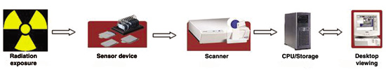 |
| Figure 1. Elements of imaging. |
 |
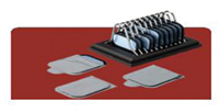 |
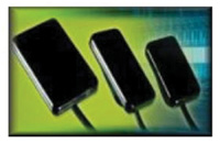
| Figure 2a. CCD image sensors. | Figure 2b. PSP image plates. |
 |
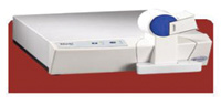 |
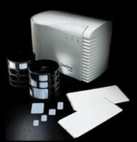
| Figure 3a. Gendex image scanner. | Figure 3b. Digora image scanner. |
The steps involved in a digital imaging cycle are illustrated in Figure 1. There are three basic components of a digital imaging system: computers (desktops, viewing stations), detectors (image acquisition devices) (Figures 2a and 2b), and scanners (Figures 3a and 3b). The computer controls acquisition, storage, processing, retrieval, and display of a digital image. Detectors are primarily used to capture or acquire images from the source and store them until they are processed. A detector converts the x-ray beam into an electronic signal. Scanners are used to process the image acquired by the detectors and convert them into digital form to be displayed on a computer screen. The electronic signal from the detector is converted from an analog form to a digital form.
Computers allow for the input and output of data. They also provide the storage functions required for easy access and retrieval of image data, and they perform these functions with great speed. Input devices are used to collect external information. These may be a keyboard or an electronic detector system. Memory is required to store both instructions to perform functions and data for processing. A central processing unit is required for processing instructions. Internal storage of data may be on hard disks, and external storage can be on CDs or zip drives. Output devices are printers and video monitors that are used to present the information in the form that can be interpreted by the user. The computer “bus” allows for the communication between all these components and makes the device functional.
DIGITAL RADIOGRAPHIC ACQUISITION
Several methods are available to acquire a digital image. A conventional radiograph can be digitized using a flatbed scanner and transparency adapter. Conventional radiographs can also be digitized using a charge couple device (CCD) video camera. There are two common types of detector or sensor systems currently available: direct digital systems and semidirect digital systems. The CCD, complementary-metal-oxide-semiconductor (CMOS), and the bulk charge modulated device are classified as direct digital systems. Direct digital systems use an electronic device consisting of a light sensitive element, and output from these devices is transferred to a computer as an electric signal and then digitized. With this system the image is displayed on the computer monitor almost immediately. Semidirect digital imaging systems use photo stimulable phosphor plates (PSP) to acquire a digital image. PSP holds a latent x-ray image that is the result of excitation of electrons in the phosphor crystals by the x-ray photons. A laser beam is used to scan the plate and a photo-multiplier device captures the resultant image. The output from the photo-multiplier is converted to pixels and displayed on a computer screen.
Image Sensors
The most common type of sensor is the CCD (Figure 2a). In CCD systems a wire connects the sensor and the computer, and the image is displayed almost immediately. The first intraoral radiography system utilized a CCD sensor and processing unit with the digital radiographic image being displayed on a computer monitor.3,4 A radiation-sensitive device inside the sensor determines the amount of voltage received from the x-ray beam. The voltage is then converted to a numerical value that is assigned to gray level displayed on the screen. The CMOS sensor is also finding acceptance in dental practice. These sensors have the same makeup as the CCD sensors except they use active pixel technology. The major advantages of the CMOS sensors are the integration of control circuits directly into the sensor, low power utilization, and low cost. Schick Technologies is a digital imaging system vendor that uses active pixel sensors with CMOS technology.
The second type of image sensor is the PSP. This type of sensor has properties similar to i
ntensifying screen phosphors. The PSP sensor consists of an imaging plate (Figure 2b). This imaging plate consists of phosphor particles embedded in a polymer binder and coated onto a plastic base.5 In a PSP system a plate is exposed to radiation and a latent image is created and stored on the plate to be scanned and transferred to a computer for viewing. As the phosphor layer of the plate is irradiated, the electrons become trapped in the detector. During processing of the plate the electrons are released and emit a blue light proportional to the intensity of the x-rays attenuated in the phosphor layer. The light is then converted to a digital form, and data is displayed on the screen. The information contained in the plate is released by exposure to a laser scanner. The storage phosphor plate is approximately the same size and body as conventional film, and there are no connecting wires. Sordex and Gendex are two vendors that use PSP technology for digital imaging.
DIGITAL IMAGE PROCESSING
Digital image enhancement in its simplest form results in a new image that is visually more appealing. Another form of image enhancement is aimed at correcting the image for known deficiences, for example to remove blur or to compensate for defective pixels in the image receptor. The most common image enhancement operations used in dentistry are contrast enhancement, filtering, digital subtraction, and color. A user can enhance the digital contrast by changing the distribution of gray values in the image without changing the image itself. Some studies have shown increased diagnostic utility of contrast enhancement in digital radiographs.6 Filtering is another method used to improve the image quality by removing features such as high-frequency noise (speckling) or low-frequency noise (intensity changes). Filters for image enhancement have been applied to dental digital radiographs to increase sharpness or reduce various types of noise.7 Digital subtraction radiography (DSR) has been developed to detect mineral changes that have occurred over time. DSR allows for more meaningful comparison of serial radiographs over time. Numerous studies have shown the high diagnostic utility of DSR.8
Image analysis operations offer meaningful functionality compared with conventional radiography. These operations are designed to extract information from the image that is diagnostically relevant. This type of information can range from a simple measurement to a fully automated classification procedure. Digital radiography allows detailed measurements; however it does not imply that these measurements are valid and that the measurements are consistent. The literature contains numerous reports on studies assessing the utility of digital measurements with applications in endodontics, orthodontics, periodontics, implantology, and other areas of dentistry. Most of these reports pertain to digital equivalents of existing methods, such as measuring length, distance, and angles. Digital length measurements using PSP plates in endodontics have been shown to be as accurate as conventional methods.9 The use of digital measurements in orthodontics has enhanced cephalometric analysis especially when combined with automated landmark identification.10 Measurement of alveolar bone height changes adjacent to teeth and implants has many applications.11 In addition, digital images have made it possible to determine bone density change within an area. Change in bone density has been used to evaluate the healing of periapical lesions after endodontic treatment.12 The overall goal of image analysis is to improve the diagnostic utility of images. The most important question remains as to whether the image is a valid and accurate representation of the patient’s status. The value of digital image processing as a part of digital imaging depends on aspects of image acquisition, as well as on aspects of vision and cognition. When used properly, image processing can improve diagnostic outcomes.
DIGITAL RADIOGRAPHIC IMAGE STORAGE
Once a radiograph is made available in digital form, it is archived in a computer. Image compression as a part of image analysis has been used to reduce the size of digital images for storage or transmission. Managing large files of images is a challenge even with the current generation of storage media and high-speed fiber-optic networks. Compression algorithms have been developed to achieve high levels of compression while retaining image quality. The compressed images are stored in standard formats in common storage systems such as hard disks, magnetic tapes, and optical devices such as DVDs or CDs. Selection of storage technology is based on storage capacity, required access speed, and cost. The fundamental question is whether a compressed image will retain its diagnostic value. Studies have explored the effects of image compression on the diagnosis of caries,13 and for determining the endodontic file length.14 These reports established that compressed images were diagnostically equivalent to uncompressed images.
DIGITAL IMAGE COMMUNICATION
Images are stored in computers in various image formats for easy communication, access, and retrieval. The challenge is to use a format that can accommodate all diagnostic imaging data, be scalable, and be shared between systems. Most dental digital systems that are being marketed today are stand-alone systems and do not necessarily interface or exchange information with each other. This means that an image obtained with a Digora scanner (Figure 2b) cannot be viewed or displayed on a Gendex user interface or viewer. This will make exchange of images between disparate systems difficult. An alliance of the American College of Cardiology, American College of Radiology (ACR), and companies that manufacture medical equipment (National Electrical Manufacturer’s Association or NEMA) developed the ACR-NEMA standard. This standard evolved into the digital image communication in medicine standard (DICOM). This standard defines a set of communication protocols allowing the interchange of information and images from different digital radiographic systems. The DICOM standard has long been used by the medical establishment and specifies file formats to allow images to be viewed across different platforms. Once manufacturers of dental equipment become compliant with the DICOM standard, dentists will be able to easily exchange images.
DIGITAL PRESENTATION AND DISPLAY
The digital image can be displayed for viewing on a desktop computer monitor screen or a laptop liquid crystal display. Studies have reported that laptop displays are diagnostically comparable with desktop monitors and conventional film for accuracy of caries detection.15 Images displayed on a computer screen need to possess fidelity, diagnostic clarity, and also be appealing to the human eye. Fidelity can be expressed in terms of spatial resolution, gray scale resolution, gray scale linearity, signal-to-noise ratio, and absence of distortion. Image clarity can be expressed in terms of diagnostic accuracy. Image appeal concerns the perceived aesthetics
of the displayed image.16
CONSIDERATIONS
The selection of a digital imaging system should consider the following questions.
(1) How will the digital image be captured or acquired? Digital images may be obtained either by using a direct image system such as a CCD device or an indirect system such as PSP, or by exposing film and then capturing the film image with a computer scanner or frame grabber. For offices that want to change from film to digital, both methods can be used. The direct system could be used for all new images, and the film-to-digital system could be used to convert existing film images to digital images.
(2) How much storage is required for digital images? This will be based on volume of radiographic images taken on a routine basis. Digital images occupy a large amount of data storage. Based on the projected radiographic image requirements for another 5 years, large capacity hard disks or optical disks will be needed to satisfy storage requirements. Additionally, image compression and decompression algorithms should also be considered to reduce the disk space needed for storage.
| Table 1. Decision-Making Grid When Purchasing a Digital Imaging System | ||||||||||||||||||||||||||||||||||||||||||||||||||||||||||||||||||||||||||||||||
|
Feature Checklist
|
||||||||||||||||||||||||||||||||||||||||||||||||||||||||||||||||||||||||||||||||
|
(3) How will the images be visualized? Computer monitors are inexpensive compared with flat screen LCD panels. When choosing a monitor, size should be considered in relation to its planned location in the office. Images can also be visualized by printing them using laser printers. Table 1 will assist in decision-making before selecting a system. A user must also have an idea of the range of specifications of components that comprise a digital dental imaging system (Table 2).
| Table 2. Computer System Requirements for Digital Imaging System | ||||||||||||||||||||||||||||||
|
CONSTRAINTS OF DIGITAL IMAGING
There are some constraints to the use of a digital system or when changing from a conventional system to a digital system. The initial cost of introducing a digital system can be high. The cost of digital imaging equipment including computer hardware can range from $20,000 to $30,000 per unit. There are significant costs associated with network installation and training. There is also a learning curve for system users. Competency takes time to acquire. There is also concern regarding infection control and care of the sensors. As with other clinical procedures, infection control is essential. Plastic bags have been used to protect the plate or sensor and also to prevent cross-contamination. It is important to remember that sensors are not disposable and if damaged can be expensive to replace. Damage can result in production of artifacts that will interfere with the diagnostic utility of the image. The cost of replacing a PSP plate is approximately $50, and a CCD detector can cost more than $6,000 per unit.
CONCLUSION
Digital imaging technology offers some distinct advantages. Computers aid in the rapid and convenient storage, retrieval, transmission, and display of radiographic images. The information can be used prospectively and/or retrospectively to develop a treatment plan or assess treatment over a period of time. In the future, the use of digital radiography will expand. There will be more practitioners using PSP and CCD technology, and advances in scanner and viewing technology will increase the amount of information obtained from digital radiography.
Acknowledgment
The authors would like to thank Dr. Ira B. Lamster, Dean of Columbia University School of Dental and Oral Surgery, for his valuable advice and help in the preparation of this manuscript.
References
1. Miles DA, Razzano MR. The future of digital imaging in dentistry. Dent Clin North Amer. 2000; 44:427-438.
2. Miles DA, Langlais RP, Parks ET. Digital x-rays are here doctor. Why aren’t you using them? J Can Dent Assoc. 1999;27:926-934.
3. Horner K, Shearer AC, Walker A, et al. Radiovisiogrpahy: an initial evaluation. Br Dent J. 1990;168:244-248.
4. Shearer AC, Horner K, Wilson NHF. Radiovisiography for imaging root canals: an in vitro comparison with conventional radiography. Quintessence Int. 1990;21:789-794.
5. Brettle DS, Workman A, Elwood RP. The imaging performance of a storage phosphor system for dental radiography. Br J Radiol. 1996;72:256-261.
6. Wenzel A. Digital radiography and caries diagnosis. Dentomaxillofac Radiol. 1998;27: 3-11.
7. Yoshioka T, Koboyashi C, Suda H, et al. Correction of background noise in direct digital dental radiography. Dentomaxillofac Radiol. 1996; 25:256-262.
8. Reddy MS, Jeffcoat MK. Methods of assessing periodontal regeneration. Periodontol. 2000;19:87-103.
9. Cederberg RA, Tidwell E, Frederiksen NL, et al. Endodontic working length assessment: comparison of storage phosphor digital imaging and radiographic film. Oral Surg Oral Med Oral Pathol Oral Radiol Endod. 1998;85:325-328.
10. Gotfredsen E, Kragskov J, Wenzel A. Development of a system for craniofacial analysis from monitor-displayed digital images. Dentomaxillofac Radiol. 1999;28:123-126.
11. Battenburg RH, Meijer HJ, Geraets WG, et al. Radiographic assessment of changes in marginal bone around endosseouses implants supporting mandibular overdentures. Dentomaxillofac Radiol. 1998;27: 221-224.
12. Delano EO, Tyndall D, Ludlow JB, et al. Quantitative radiographic follow-up of apical surgery: A radiometric and histologic correlation. J Endod. 1998;24:420-426.
13. Wenzel A, Gotfredsen E, Borg E, et al. Impact of lossy image compression on accuracy of caries detection in digital images taken with a storage phosphor system. Oral Surg Oral Med Oral Pathol Oral Radiol Endod. 1996; 81:351-355.
14. Van der Stelt PF, Sanderink GCH, Dula K. Lossy file compression and diagnostic image quality of digital intraoral radiographic images [abst 1010]. J Dent Res. 1996;75(spec iss):128.
15. Lim KF, Loh E E-M, Hong YH. Intra-oral computed radiography: an in vitro evaluation. J Dent. 1996;24:359-364.
16. Kundel HL. Visual perception and image display terminals. Radiol Clin North Am. 1986;24:69-78.
Dr. Pai is an assistant professor of clinical dentistry and director of clinical information systems at the Columbia University School of Dental and Oral Surgery in New York City.
Dr. Zimmerman is an associate professor of clinical dentistry and assistant dean for information resources at the Columbia University School of Dental and Oral Surgery in New York City.

